Pneumatic tyre tread comprising a plurality of incisions

A tire tread, sipe technology, applied in tire tread/tread pattern, tire parts, transportation and packaging, etc., can solve problems such as energy loss

Active Publication Date: 2013-05-15
OCIETE DE TECH MICHELIN
View PDF8 Cites 5 Cited by
  • Summary
  • Abstract
  • Description
  • Claims
  • Application Information

AI Technical Summary

Problems solved by technology

This sidewall deformation leads to energy loss through the hysteresis effect

Method used


Image

  • Pneumatic tyre tread comprising a plurality of incisions
  • Pneumatic tyre tread comprising a plurality of incisions
  • Pneumatic tyre tread comprising a plurality of incisions

Examples


Embodiment Construction

[0060] In the following description, the same reference numerals will indicate the same or similar elements.

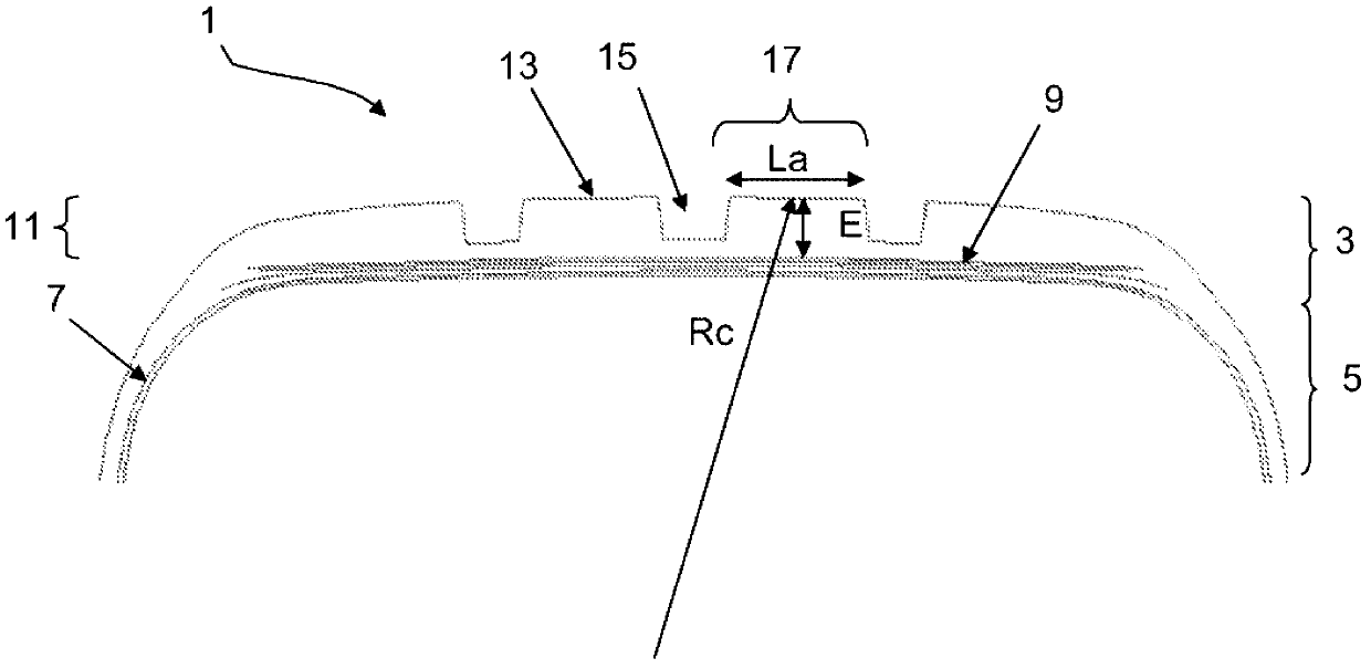
[0061] figure 1 A partial sectional view of the tire 1 is schematically depicted.

[0062] The tire 1 comprises a crown comprising a crown region 3 extending laterally by a sidewall 5 connected to a bead (not shown) intended to come into contact with a mounting rim.

[0063] The tire 1 comprises a carcass reinforcement 7 extending from one bead to the other via the sidewalls 5 and the crown region 3 .

[0064] The crown region 3 comprises a reinforcement 9 covered radially on the outside by a tread 11 .

[0065] The tread 11 includes, on the radially outer side, a tread surface 13 intended to contact the ground when the vehicle is running.

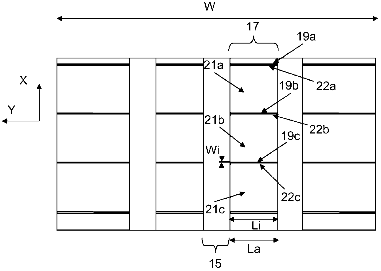
[0066] The tread 11 includes a plurality of grooves 15 .

[0067] The grooves 15 delimit a raised circumferential band 17 .

[0068] Each circumferential band 17 has a contact surface intended to contact the ground when the t...


PUM


Abstract

The invention relates to a pneumatic tyre tread of width W. This tread comprises a central region of a width of between 70% and 80% of the width W of the tread. The central region comprises one or more circumferential strips (17), each circumferential strip of the central region being delineated by two grooves of a width greater than or equal to 2 mm. Each circumferential strip of the central region comprises a contact surface intended to come into contact with the ground and a plurality of transverse incisions (19a, 19b, 19c) distributed uniformly in the circumferential direction. Each incision on the contact surface has a width of less than 2 mm so as to define an average circumferential cuts ratio. This average circumferential cuts ratio is between 0.5 times and 1.5 times the ratio between a mean thickness (E) of the circumferential strip and a mean circumferential radius of curvature (Rc) of said circumferential strip. The incisions divide the circumferential strip into a succession of blocks (21, 21b, 21c), each block having two edges (22a, 22b, 22c, 24) that intersect the contact surface of the circumferential strip. For each block of the circumferential strip, at least one of the edges of said block is extended radially by an inclined part (29a, 29b, 29c, 31) that forms a chamfer. This inclined part connects the edge to a side wall of the block in order to generate a circumferential offset between said edge and said side wall of the block.

Description

technical field [0001] The present invention relates to a tire tread comprising a plurality of sipes and related components for reducing the rolling energy consumption of the tread. The invention relates in particular to tire treads intended for fitting to passenger motor vehicles. Background technique [0002] Reducing the energy consumption associated with the forward movement of a vehicle is an important goal pursued by all motor vehicle manufacturers and builders. This goal usually governs tire development and marketing. [0003] To reduce this energy consumption, one solution is to reduce the rolling resistance of the tire. [0004] It is known that the rolling resistance of a driven tire is related to the energy losses within said tire. These energy losses depend on the hysteresis properties of the rubber compound used in the tread. These energy losses also depend on the deformation cycles the tread undergoes when the tire is driven. [0005] More specifically, th...

Claims


Application Information

Patent Timeline
Patent Type & Authority Applications(China)
IPC IPC(8): B60C11/12B60C11/13
CPCB60C2011/129B60C11/1392B60C11/124B60C11/13B60C2011/1338B60C2011/1209B60C11/1272B60C11/1281B60C11/12B60C11/0306B60C11/125
Inventor C·吉耶尔穆E·贝尔热
Owner OCIETE DE TECH MICHELIN
Why Eureka
Try Eureka