Scalable connection system for parallel wiring circuits

A technology of electrical connection and wiring, applied in the direction of connection, circuit, circuit or fluid pipeline, etc., which can solve the problem of expensive metal

Active Publication Date: 2015-04-15
LEAR CORP
View PDF6 Cites 0 Cited by
  • Summary
  • Abstract
  • Description
  • Claims
  • Application Information

AI Technical Summary

Problems solved by technology

The high current and heat requirements require the use of copper wiring, which is more expensive and heavier than metals such as aluminum

Method used


Image

  • Scalable connection system for parallel wiring circuits
  • Scalable connection system for parallel wiring circuits
  • Scalable connection system for parallel wiring circuits

Examples


Embodiment Construction

[0017] Reference will now be made in detail to presently preferred constructions, embodiments and methods of the invention, which constitute the best modes of carrying out the invention presently known to the inventors. Images are not necessarily to scale. It should be understood, however, that the disclosed embodiments are merely exemplary of the invention, which may be embodied in various and alternative forms. Therefore, specific details disclosed in these embodiments are not to be interpreted as limiting, but merely as a representative basis for any aspect of the invention and / or as a representative basis for teaching one skilled in the art to variously employ the invention. basis of sex.

[0018] Except in the examples, or where otherwise expressly indicated, all numerical quantities in this specification expressing amounts of materials or conditions of reaction and / or use are to be understood as modified by the word "about" to describe the broadest scope of the inventio...


PUM


Abstract

A high voltage connector system includes a first header for connection to a first electronic device, a first connector that connects to the first header, a second header that connects to a second electronic device, a second connector that connects to the second header, and a plurality of wires connecting the first connector and the second connector. The first header includes a first plurality of header terminals that are electrically connected together such that a high voltage electric current is divided into a plurality of sub-currents. The second header has a second plurality of header terminals that are electrically connected together such that the plurality of sub-currents are joined together to reform the first high voltage electric current.

Description

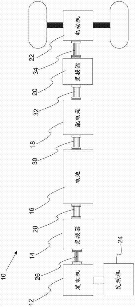
technical field [0001] The present invention relates to electrical connection systems for use in high voltage applications, and in particular to electrical connection systems for use in hybrid vehicles. Background technique [0002] Electric vehicles and hybrid vehicles are becoming more and more common. Such vehicles are usually provided with a high-voltage battery and an electric, battery-driven electric motor. Additionally, these vehicles typically feature inverters, generators, distribution boxes, and other high voltage components. [0003] Electric vehicles and hybrid vehicles require electrical connection systems that operate at high voltages and high currents between 150 amps and 400 amps. Such connection systems usually include high gauge wiring and so can appear to be very inflexible, making it difficult to be integrated into the vehicle. Thicker wiring tends to be somewhat inefficient for heat dissipation. The high current and heat requirements require the use ...

Claims


Application Information

Patent Timeline
Patent Type & Authority Patents(China)
IPC IPC(8): B60R16/02
CPCH01R31/02B60L11/1816Y02T90/14Y02T90/121B60L2230/12B60L11/1818Y02T10/7088Y02T10/7005B60L2210/30B60L2210/40B60L2240/36Y04S30/14B60L53/16B60L50/61B60L53/65B60L53/18Y02T10/62Y02T10/7072Y02T10/72Y02T90/12Y02T90/167Y02T10/70Y02T90/16
Inventor 斯洛博丹·帕夫诺维奇大卫·曼泽斯莱因哈德·普施迈克尔·哈代
Owner LEAR CORP
Why Eureka
Try Eureka