
Material transfer unit for automobile production lines

A technology of automobile production line and equipment, which is applied to trolleys, motor vehicles, multi-axis trolleys, etc., can solve the problems of prone to errors and omissions, mixed placement, and failure to meet the production requirements of batch assembly lines, so as to reduce storage, improve error prevention and protection. Effect

Active Publication Date: 2013-05-22
ANHUI JIANGHUAI AUTOMOBILE GRP CORP LTD
View PDF7 Cites 9 Cited by
  • Summary
  • Abstract
  • Description
  • Claims
  • Application Information

AI Technical Summary

Problems solved by technology

[0002] At the present stage, most automobile manufacturers use special-purpose or general-purpose workstations on the side of the production line for temporary storage of production materials. For special-purpose workstations, the material switching method generally adopted is to directly switch between full and empty workstations. Station equipment, therefore, it must be ensured that at least two of the station equipment are placed next to the production line to meet the beat impact caused by equipment switching. The disadvantage of this method is that it increases the occupied area of ​​materials next to the production line. Universal station equipment is suitable Due to the storage of various materials, the resulting disadvantage is that the material personnel are easy to mix the materials when changing the materials, and the operator must spend a certain amount of time to identify the materials, which not only affects the working time but also is prone to errors and omissions.
To sum up, whether it is in terms of material storage space or vehicle quality control, the above-mentioned automotive production line material storage station equipment can no longer meet the requirements of batch assembly line production.

Method used


Image

  • Material transfer unit for automobile production lines
  • Material transfer unit for automobile production lines
  • Material transfer unit for automobile production lines

Examples


Embodiment Construction

[0020] The following examples illustrate the technical solutions of the present invention in detail. It should be understood that the following embodiments can only be understood as explanations and descriptions of the technical solutions of the present invention and cannot be construed as limitations on the technical solutions of the present invention.

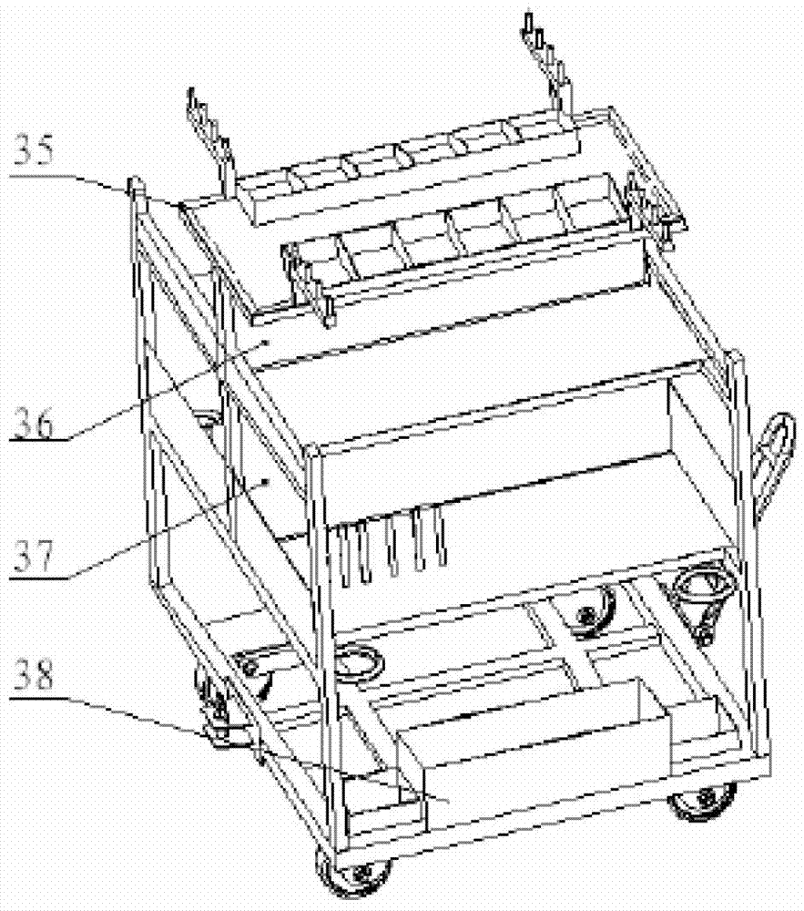
[0021] figure 1 This is a schematic diagram of the structure of the material transfer equipment for the automobile production line of the present invention; the figure shows the large material box 38 located in the bottom frame, the lower middle partition 37 and the upper middle partition 36 arranged on the second layer frame and the third layer frame, The uppermost frame 35.

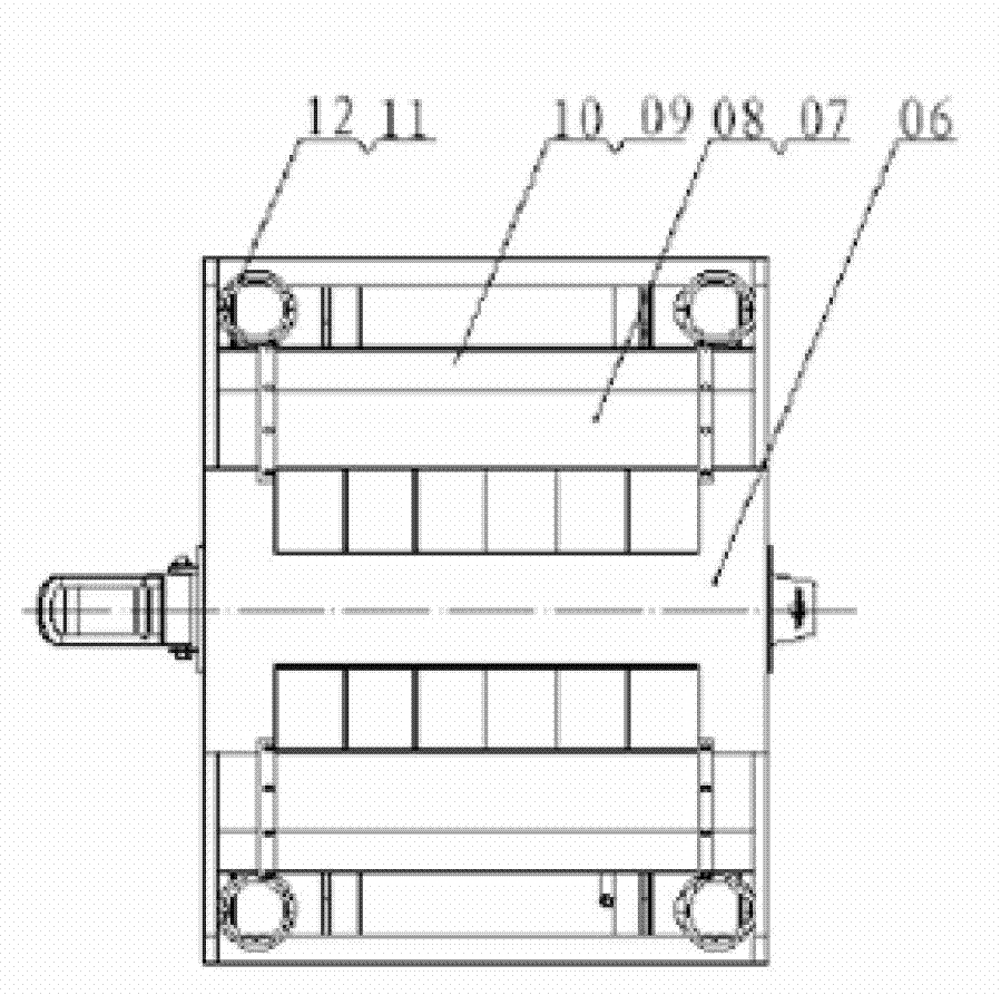
[0022] figure 2 for figure 1 The top view of the transfer equipment, which shows the first layer 6, the second layer 7 and the third layer 9 between two adjacent frames; the second layer 7 is provided with the second layer The board protection pad 8 is pro...


PUM


Abstract

The invention relates to a material transfer unit for automobile production lines. The material transfer unit comprises a multilayer frame structure formed by at least four vertical tubes fixed together and adjustable universal wheels fixed on a bottom frame. One end of each vertical tube is fixedly connected to the bottom frame. A shelf is disposed between each two adjacent layers of the multilayer frame. The multilayer frame structure is provided with corresponding layered structures according to different weights, sizes and shapes of automobile parts to be transferred. A pull bar and a draw bar are disposed at front and rear ends of the transfer unit respectively. The material transfer unit for automobile production line is applicable to classified storage of various automobile parts, better prevents mistaken placement of materials and better protects the materials. Effective connection between the front pull bar and the rear draw bar enables the material transfer unit to more adapt to material supply and transfer for batch production lines.

Description

Technical field [0001] The invention belongs to the field of automobile assembly process components, and particularly relates to a material transfer equipment for an automobile production line. Background technique [0002] At the present stage, most automobile manufacturers use special workstations or general-purpose workstations on the side of the production line for temporary storage of production materials. The material switching method commonly used for special workstations is to directly switch to empty workstations. Work station equipment, therefore, it is necessary to ensure that at least two of the station equipment are placed next to the production line to meet the tempo impact caused by the equipment switching. The disadvantage of this method is that it increases the occupied area of ​​materials next to the production line. General-purpose work station equipment is suitable Due to the storage of multiple materials, the resulting disadvantage is that the material person...

Claims


Application Information

Patent Timeline
Patent Type & Authority Applications(China)
IPC IPC(8): B62B3/00
Inventor 张继光
Owner ANHUI JIANGHUAI AUTOMOBILE GRP CORP LTD
Learn More