Hydraulic drive pressure reducing valve for wind tunnel

A pressure reducing valve and hydraulic technology, applied in the field of pressure reducing valves, can solve the problems of inability to adjust the pressure in the wind tunnel and fail to meet the requirements, and achieve the effects of short fully open and fully closed times, reduced test costs, and low friction.

Active Publication Date: 2013-05-22
CHINA ACAD OF AEROSPACE AERODYNAMICS
View PDF6 Cites 2 Cited by
  • Summary
  • Abstract
  • Description
  • Claims
  • Application Information

AI Technical Summary

Problems solved by technology

Existing industrial valves did not meet the requirements and therefore could not be used for pressure regulation in wind tunnels

Method used


Image

  • Hydraulic drive pressure reducing valve for wind tunnel
  • Hydraulic drive pressure reducing valve for wind tunnel
  • Hydraulic drive pressure reducing valve for wind tunnel

Examples


Embodiment Construction

[0015] The principles and features of the present invention will be described in detail below in conjunction with the accompanying drawings.

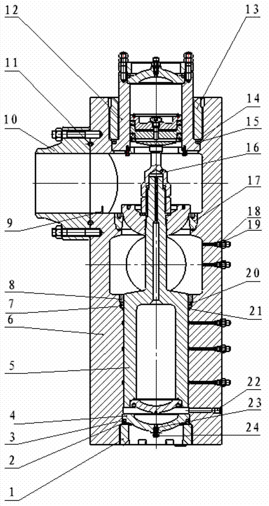
[0016] Such as figure 1 As shown, the hydraulically driven pressure reducing valve of the present invention includes: nut 1, backing ring 2, sealing ring 3, lower cover 4, pressure regulating piston 5, valve body 6, backing ring 7, movable nut 8, retaining ring 9, method Lan 10, gasket 11, closing piston 12, nut 13, backing ring 14, sealing ring 15, rod 16, disc seat 17, sealing ring 18, nozzle 19, sealing ring 20, felt ring 21, oil pipe nozzle 22, sealing Ring 23 and nozzle 24. When the pressure reducing valve is closed, the closing piston 12 will press the pressure regulating piston 5 tightly through the rod 16. When the pressure reducing valve is opened, the gas flow will be injected through the air inlet of the pressure reducing valve, and the pressure regulating piston 5 will inject hydraulic pressure through the oil nozzle 22 at ...


PUM


Abstract

The invention discloses a hydraulic drive pressure reducing valve for a wind tunnel. The hydraulic drive pressure reducing valve for the wind tunnel comprises an air inlet, an air outlet, a valve body (6), a closing piston (12), a pressure adjusting piston (5), a rod (16), an oil pipe mouth (22) and a plate base (17). The pressure adjusting piston (5) includes a piston body (51), plates (52), gaskets (53), nuts (54), seal rings (55, 56) and an upper cover (57). The closing piston (12) comprises a cover (128), inner pistons (127), outer pistons (126), roller bodies (122) and a filler neck (1216). According to the hydraulic drive pressure reducing valve for the wind tunnel, the profile curves of the plates are designed to be elliptic characteristic curves, and therefore the pressure reducing valve in the working state is enabled to obtain linear or close to linear regulating characteristics. Meanwhile, the hydraulic drive pressure reducing valve for the wind tunnel has the advantages of being good in airflow symmetry properties, wide in adjusting range, short in time of full opening and full closing , and capable of completing a wind tunnel blowing experimental task with a mach number range of 5-8.

Description

technical field [0001] The invention relates to a pressure reducing valve, in particular to a hydraulically driven pressure reducing valve used in a hypersonic wind tunnel. Background technique [0002] Wind tunnels have always played a very important role in aerodynamic research and aircraft design. Many important theories of aerodynamics are proposed after a large number of observations in wind tunnel experiments, and their applications have been verified by wind tunnel experiments. The pressure reducing valve is an important part of the wind tunnel. In the hypersonic wind tunnel, it reduces the inlet pressure to a certain required outlet pressure through the throttling of the opening and closing parts, and can use itself when the inlet pressure and flow change. The energy of the medium keeps the outlet pressure basically constant, and it can be used as a pressure regulating device to complete the primary pressure regulating task of the wind tunnel. During the operation ...

Claims


Application Information

Patent Timeline
Patent Type & Authority Applications(China)
IPC IPC(8): F16K1/12F16K31/122F16K27/02
Inventor 沈逢京崔旭石运军陈良泽黄景博卜俊辉李玉秋崔春孙勇堂孙涛穆东波赵小运
Owner CHINA ACAD OF AEROSPACE AERODYNAMICS
Why Eureka
Try Eureka