
Gas decompressor

A pressure reducer and gas technology, applied to valve details, cocks including cut-off devices, engine components, etc., can solve the problems of limited adjustment range and low adjustment accuracy, and achieve a large pressure adjustment range, simple structure, and stable performance. Effect

Inactive Publication Date: 2019-04-12
BEIJING AEROSPACE TECH INST
View PDF4 Cites 1 Cited by
  • Summary
  • Abstract
  • Description
  • Claims
  • Application Information

AI Technical Summary

Problems solved by technology

[0003] However, in the prior art, the pressure is usually adjusted through the axial movement of the spool. This adjustment method not only has a limited adjustment range, but also has low adjustment accuracy.

Method used


Image

  • Gas decompressor
  • Gas decompressor
  • Gas decompressor

Examples


Embodiment Construction

[0020] Specific embodiments of the present invention will be described in detail below in conjunction with the accompanying drawings. In the following description, for purposes of explanation and not limitation, specific details are set forth in order to provide a thorough understanding of the invention. It will be apparent, however, to one skilled in the art that the present invention may be practiced in other embodiments that depart from these specific details.

[0021] It should be noted here that, in order to avoid obscuring the present invention due to unnecessary details, only the device structure and / or processing steps closely related to the solution according to the present invention are shown in the drawings, and the steps related to the present invention are omitted. Invent other details that don't really matter.

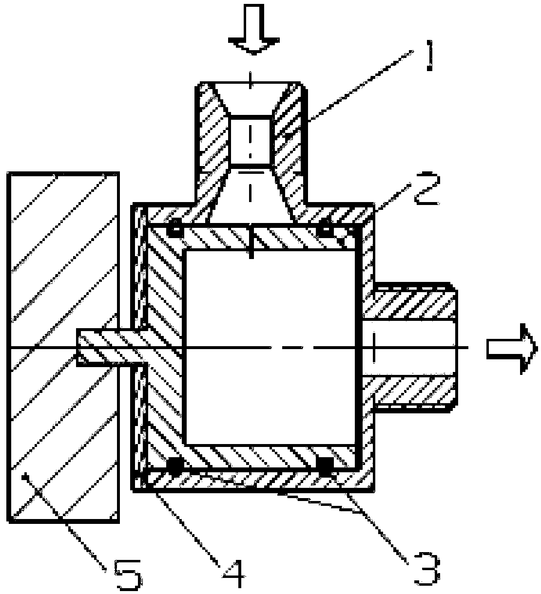
[0022] figure 1 It is a schematic diagram of the overall structure of a gas pressure reducer provided by an embodiment of the present invention.

[00...


PUM


Abstract

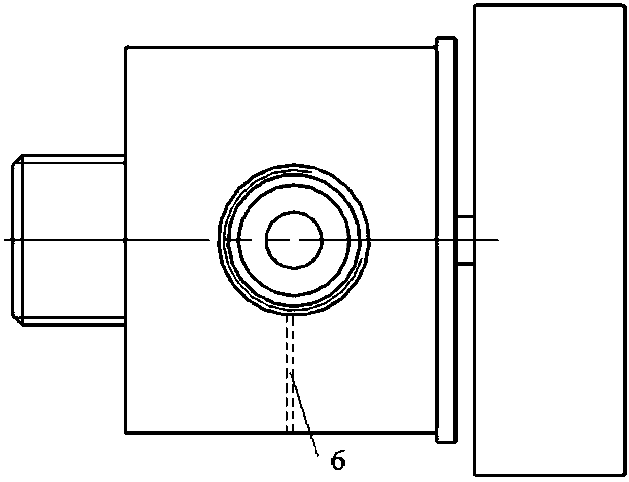
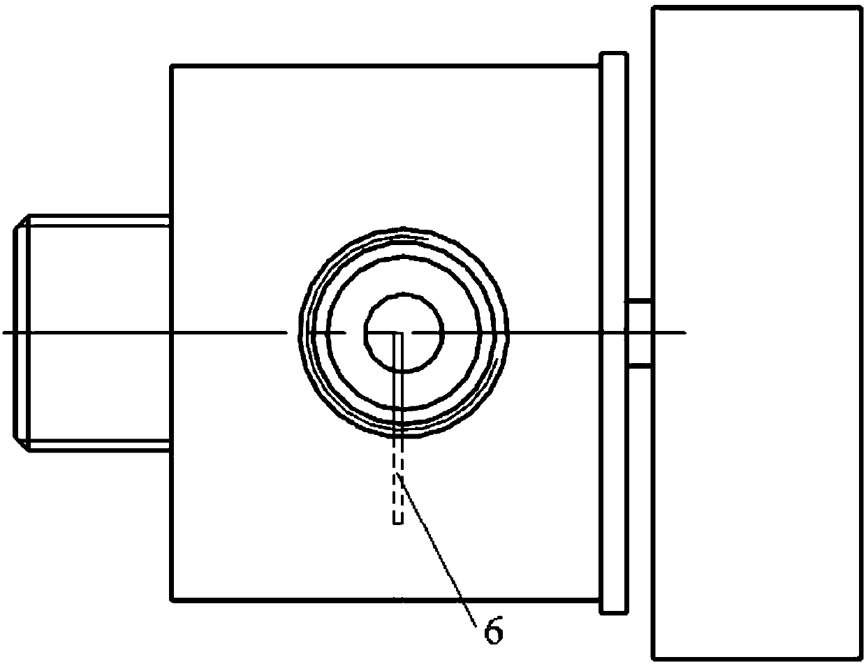
The invention relates to the technical field of gas pipeline control, and discloses a gas decompressor. The gas decompressor comprises a decompressor shell, a valve element, a valve cover and a stepping motor; the decompressor shell comprises a high-pressure chamber, a low-pressure chamber, a decompressor inlet communicating with the high-pressure chamber and a decompressor outlet communicating with the low-pressure chamber; the stepping motor is connected with the valve element and used for controlling circumferential motion of the valve element in the decompressor shell, the valve cover restricts axial motion of the valve element, and a circumferential slit groove is formed in the cylinder surface, communicating with the decompressor shell, of the valve element; and when the valve element rotates to the condition that the slit groove is in contact with the high-pressure chamber, and gas coming from the decompressor inlet and entering from the high-pressure chamber through throttlingof the slit groove enters the low-temperature chamber and flows out from the decompressor outlet. The pressure of the decompressor outlet can be adjusted in a wide-range and high-precision mode, and decompression of the gas is realized.

Description

technical field [0001] The invention relates to the technical field of gas pipeline control, in particular to a gas pressure reducer. Background technique [0002] Pressure reducers are widely used in infrastructure, chemical industry, energy, aerospace and aerospace fields. Among them, in missiles and rockets, the pressure reducer can be used in the pressurization system of the fuel tank, and the gas in the high-pressure cylinder is decompressed and then enters the fuel tank at a certain pressure to achieve pressurization. As a regulating valve, the pressure reducer adjusts the inlet pressure to the required outlet pressure through the throttling effect of the spool, and further adjusts the opening of the spool through the feedback of the outlet pressure to maintain the stability of the outlet pressure. [0003] However, in the prior art, the pressure is usually adjusted through the axial movement of the spool, which not only has a limited adjustment range, but also has lo...

Claims


Application Information

Patent Timeline
Patent Type & Authority Applications(China)
IPC IPC(8): F16K5/04F16K27/04F16K31/04
CPCF16K5/0407F16K5/0471F16K27/041F16K31/041
Inventor 左盼赵桂杰张航张聪向安定于鹏
Owner BEIJING AEROSPACE TECH INST
Learn More