
Safe inflation device

An inflatable device, a safe technology, applied in gas/liquid distribution and storage, pipeline systems, mechanical equipment, etc., can solve the problems of high opening pressure, limited exhaust speed, and inability to reduce, and achieve rapid exhaust pressure relief, The effect of ensuring safety and improving convenience

Inactive Publication Date: 2021-04-09
HUAZHONG PHOTOELECTRIC TECH INST (CHINA SHIPBUILDING IND CORP THE NO 717 INST)
View PDF7 Cites 0 Cited by
  • Summary
  • Abstract
  • Description
  • Claims
  • Application Information

AI Technical Summary

Problems solved by technology

Since the spring force is not sensitive to the change of the distance, the sensitivity is low, and the opening pressure is relatively large, often above 0.5MPa
At the same time, since the spring force is proportional to the opening degree of the overflow valve, the greater the opening degree, the greater the internal pressure of the valve core, the exhaust speed is limited, the pressure drop is small, and the pressure in the air circuit cannot be quickly released. significantly reduced to within the safe range

Method used


Image

  • Safe inflation device
  • Safe inflation device
  • Safe inflation device

Examples


Embodiment Construction

[0021] Embodiments of the present invention will be described in detail below in conjunction with the accompanying drawings.

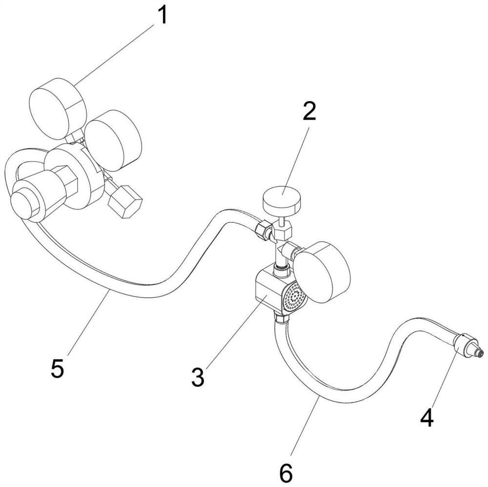
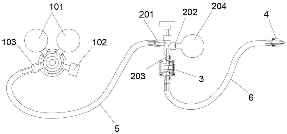
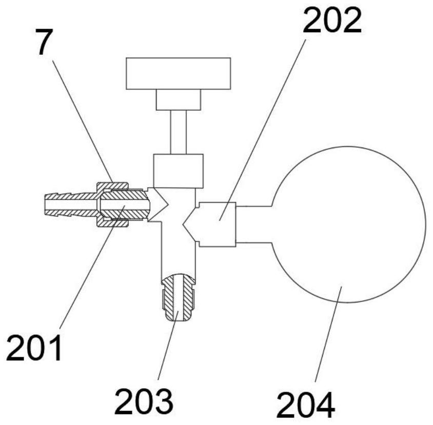
[0022] like figure 1 As shown, the technical solution of this embodiment includes a pressure reducer 1, a three-way valve 2, a safety valve 3 and an anti-twisting air nozzle 4. 5 is connected to the air inlet 201 of the three-way valve 2. There are two air outlets on the three-way valve 2, one of which is equipped with a small-range pressure gauge 204 on the air outlet 202, and the other air outlet 203 is connected to the air inlet of the safety valve 3. The air outlet 307 of the safety valve 3 is connected to the anti-twisting air nozzle 4 through the low-pressure pipe 6, and the anti-twisting air nozzle 4 is used to connect the air filling port of the optical cavity; the safety valve 3 is provided with an air pressure adjustment device , which can release the pressure of the high-pressure gas passing through the safety valve 3 .

[0023] In this em...


PUM


Abstract

The invention provides a safe inflation device. The safety inflation device can be used for periodically inflating dry nitrogen into an optical cavity with a large optical window for drying and pressure maintaining, and is simple in structure, low in cost and high in safety performance. According to the technical scheme, the safe inflation device comprises a pressure reducer, a three-way valve, a safety valve and an anti-twist air tap, wherein an air inlet of the pressure reducer is connected with an air source; an air outlet is connected with the air inlet of the three-way valve through a high-pressure pipe; two air outlets are formed in the three-way valve, one air outlet is provided with a small-range pressure gauge, and the other air outlet is connected with the air inlet of the safety valve; the air outlet of the safety valve is connected with the anti-twist air tap through a low-pressure pipe; the anti-twist air tap is used for being connected with an inflation inlet of the optical cavity; and an air pressure adjusting device is arranged in the safety valve and can release pressure of high-pressure air passing through the safety valve.

Description

technical field [0001] The invention relates to the field of air-inflating drying and pressure-holding devices for optical cavities in optoelectronic equipment, in particular to a safety inflating device. Background technique [0002] Various photoelectric sensors and optical components are installed inside the optical cavity of the optoelectronic device. In order to avoid fogging, mildew and corrosion on the surface of optical components, and improve the life of optical components and the reliability of optoelectronic equipment, it is often necessary to seal the optical cavity and periodically fill it with dry nitrogen for drying and pressure maintenance. [0003] Limited by the optical window, especially the large optical window and the structural strength of the cavity, the pressure that the optical cavity of the optoelectronic device can withstand usually does not exceed 0.1Mpa, and the safe inflation pressure is usually between 0.005MPa and 0.03MPa. The nitrogen gas so...

Claims


Application Information

Patent Timeline
Patent Type & Authority Applications(China)
IPC IPC(8): F17D1/02F17D3/01
CPCF17D1/02F17D3/01
Inventor 欧卫林常小轩陶新李鲲孙菲
Owner HUAZHONG PHOTOELECTRIC TECH INST (CHINA SHIPBUILDING IND CORP THE NO 717 INST)
Learn More