
Engine and cam shaft device thereof

A technology of camshaft and wheel disc, applied in the direction of engine components, machine/engine, valve device, etc., can solve the problems of high inertia at high rotation, unsuitable engine, difficulty in starting, etc.

Inactive Publication Date: 2015-03-04
CHONGQING YINGANG YITONG TECH
View PDF5 Cites 0 Cited by
  • Summary
  • Abstract
  • Description
  • Claims
  • Application Information

AI Technical Summary

Problems solved by technology

The disadvantage is that the valve mechanism is a reciprocating motion, and the mass of the external parts is large, and the high-speed inertia is large. Under the extremely high-speed operation, the tappet will jump off the rocker arm due to inertia and generate noise. Therefore, this type of engine is not suitable for relatively high-speed operation. surroundings
Due to the large air pressure ratio of large-displacement vehicles, if this kind of camshaft is used, there will be a problem of difficulty in starting, so at present this kind of camshaft is only suitable for small-displacement vehicles

Method used


Image

  • Engine and cam shaft device thereof
  • Engine and cam shaft device thereof
  • Engine and cam shaft device thereof

Examples


Embodiment Construction

[0019] The following will clearly and completely describe the technical solutions in the embodiments of the present invention with reference to the accompanying drawings in the embodiments of the present invention. Obviously, the described embodiments are only some, not all, embodiments of the present invention. Based on the embodiments of the present invention, all other embodiments obtained by persons of ordinary skill in the art without making creative efforts belong to the protection scope of the present invention.

[0020] The core of the invention is to provide a camshaft device, which can meet the requirements of large displacement and small displacement engines at the same time, and reduce the development cost. Another core of the present invention is to provide an engine including the above-mentioned camshaft device.

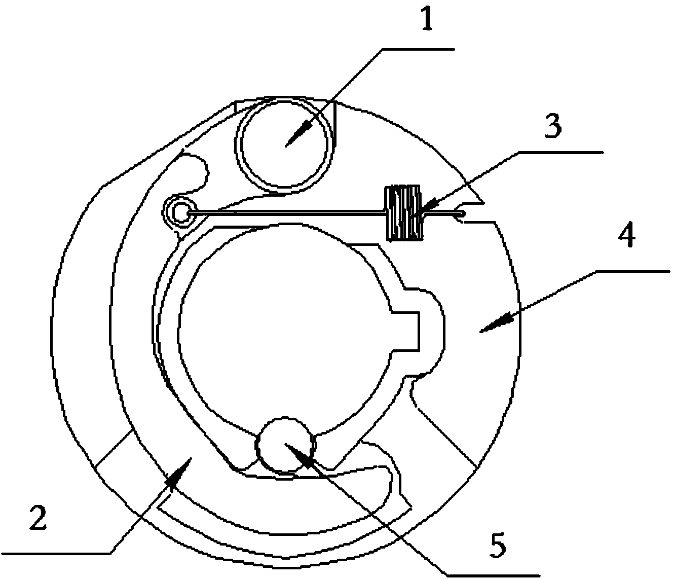
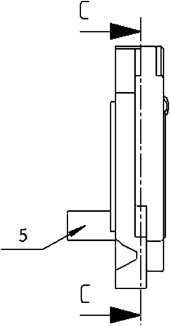
[0021] Please refer to Figure 2 to Figure 4 , figure 2 It is a front view of a specific embodiment of the camshaft device provided by the present i...


PUM


Abstract

The invention discloses a cam shaft device which comprises a cam shaft, a cam and a decompression mechanism assembly, wherein the decompression mechanism assembly is detachably connected to the side, in contact with a push rod, of the cam shaft; the decompression mechanism assembly comprises a wheel disc with a central shaft hole, a decompression part hinged to the wheel disc, a semi-cylindrical pin shaft, a spring fixedly connected with the decompression part and a shift rod connected with the decompression part; the tension force of the spring on the decompression part faces to the center of the wheel disc; the shift rod is connected with the semi-cylindrical pin shaft in an insertion manner, the pin shaft is inserted into a through hole in the wall of the central shaft hole and a clamping groove in the base circle of the cam shaft, the central shaft of the pin shaft is parallel to that of the cam shaft, and when the spring is in a free state, the semi-cylindrical pin shaft laterally stands in the through hole and is higher than the side boundary of the base circle. According to the device, the development cost of different types of engines is saved. The invention further discloses an engine with the cam shaft device.

Description

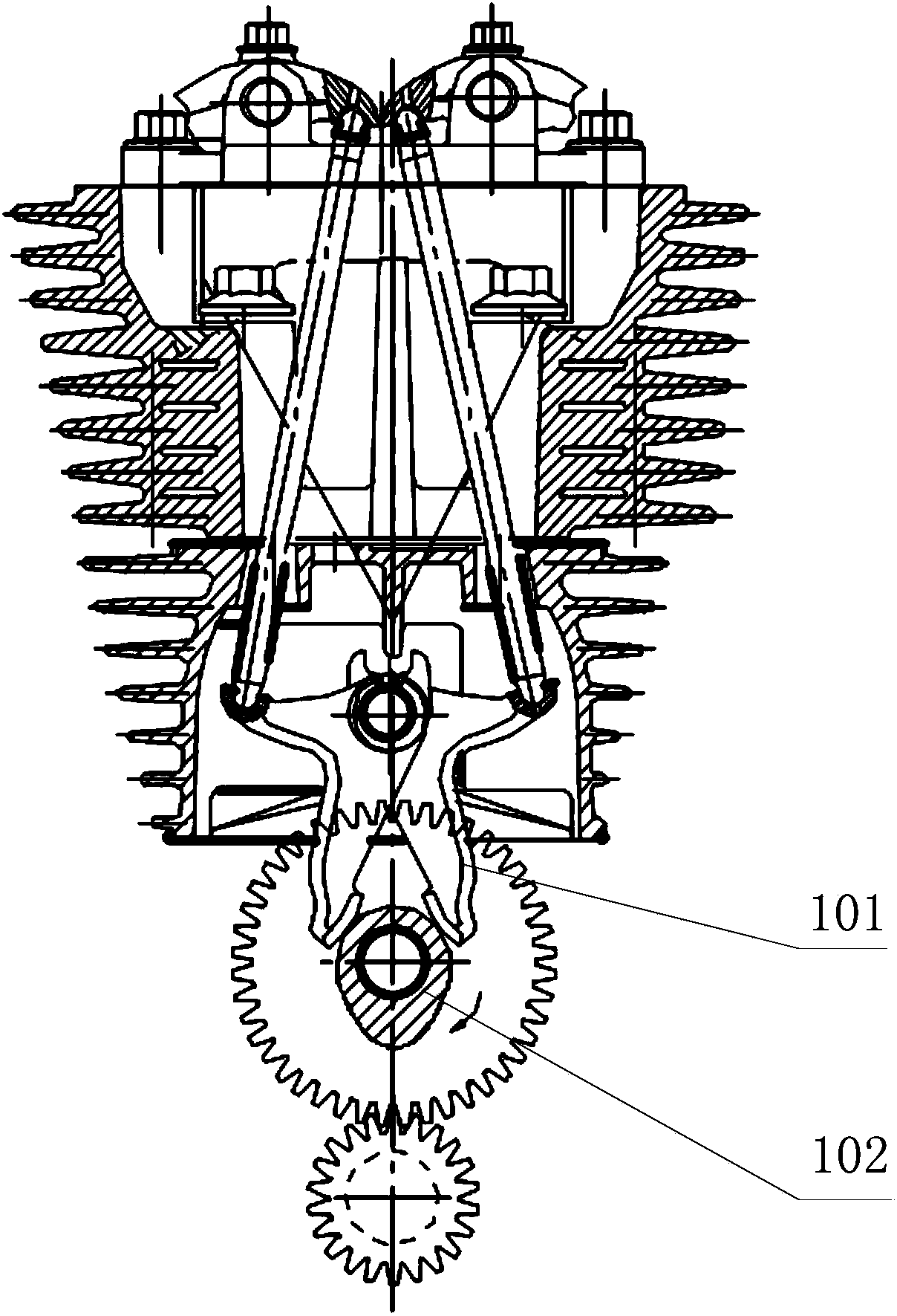
technical field [0001] The invention relates to the technical field of engineering machinery, in particular to a camshaft device. Furthermore, the present invention also relates to an engine comprising the above-mentioned camshaft device. Background technique [0002] The existing engine adopts the ejector engine valve mechanism, which is composed of valve rocker arm, tappet, lower rocker arm 101 and camshaft device 102, please refer to figure 1 , figure 1 It is a schematic diagram of a design scheme of a camshaft device in the prior art. The cam mechanism is in the crankcase, and such a structure is a lower cam engine, which is a relatively primitive structure, and its advantage is that the structure is simple and reliable. The disadvantage is that the valve mechanism is a reciprocating motion, and the mass of the external parts is large, and the high-speed inertia is large. Under the extremely high-speed operation, the tappet will jump off the rocker arm due to inertia ...

Claims


Application Information

Patent Timeline
IPC IPC(8): F01L1/047
Inventor 伍良前邹永波肖冬
Owner CHONGQING YINGANG YITONG TECH
Learn More