Three-stage pressure reducing valve

A pressure reducing valve and pressure reducing chamber technology, applied in the field of pressure reducing valves, can solve the problems of high labor intensity, difficult maintenance, affecting the effect of secondary and tertiary decompression, etc., to reduce damage and increase the range of applicable temperature difference Effect

Pending Publication Date: 2021-05-14
ZHEJIANG YUANYAO VALVE IND
View PDF6 Cites 0 Cited by
  • Summary
  • Abstract
  • Description
  • Claims
  • Application Information

AI Technical Summary

Problems solved by technology

[0003] However, the ordinary three-stage pressure reducing valve can only reduce the intake pressure of 2200psi to about 200psi through the first stage of decompression, resulting in a larger range of two-stage and three-stage decompression. The third-stage mechanism is relatively large, and the probability of damage during long-term use is higher than that of the first-stage and second-stage pressure reducing valves. The traditional pressure reducing valve is mostly a split structure in the first-stage pressure reducing mechanism, and the valve body needs to be removed during maintenance. It can be repaired only when it is disassembled. Difficult maintenance will affect the decompression effect of the second and third stages

Method used


Image

  • Three-stage pressure reducing valve
  • Three-stage pressure reducing valve
  • Three-stage pressure reducing valve

Examples


Embodiment

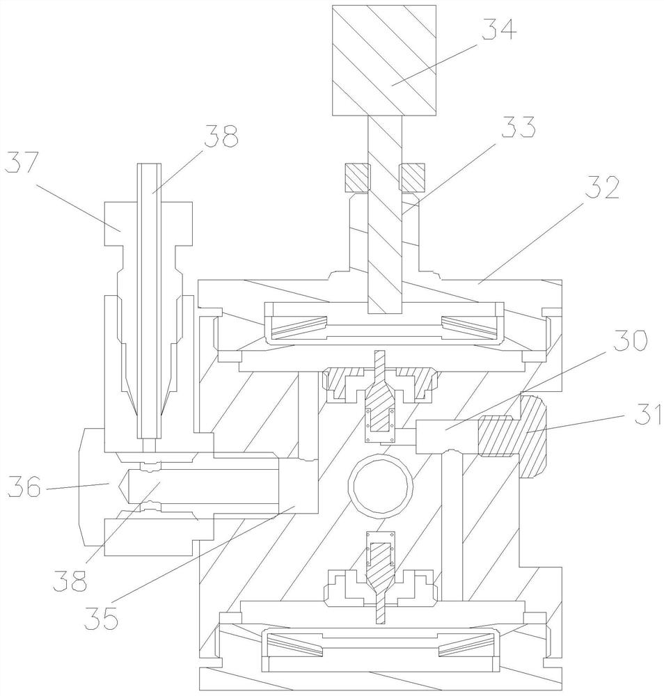
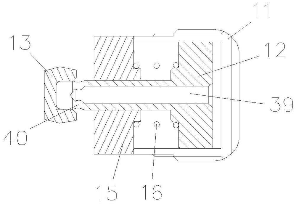
[0017] Embodiment: a kind of three-stage decompression valve, such as Figure 1-Figure 3 As shown, 1. includes a valve body 1, characterized in that: the right end of the valve body 1 is provided with a first-stage decompression chamber 2, and the left side of the valve body 1 is provided with an air intake hole 3, and the valve body 1 The lower end of the valve body 1 is provided with a secondary decompression chamber 4, and the upper end of the valve body 1 is provided with a tertiary decompression chamber 5, and the inlet port 3 communicates with the primary decompression chamber 2, and the primary decompression chamber 2 communicates with the secondary decompression chamber 4, and the bottom end of the air intake hole 3 is provided with a filter element 6, and the primary decompression chamber 2 is fixedly connected with a compression nut 11 through threads, and the compression nut The inside of 11 is slidingly equipped with a piston rod 12, the right end of the piston rod...


PUM


Abstract

The invention discloses a three-stage pressure reducing valve, and belongs to the technical field of pressure reducing valves. According to the three-stage pressure reducing valve, a compression nut is fixedly connected into a first-stage pressure reduction chamber through threads, a piston rod is arranged in the compression nut in a sliding fit mode, the right end of the piston rod is sleeved with a valve bonnet, the piston rod, the valve bonnet, a piston ring and a piston bush are arranged in the compression nut in a unified mode, pressure reduction of gas is realized through front-back movement of the piston rod, when the first-stage pressure reduction chamber needs to be maintained, the piston rod and other ancillary parts in the first-stage pressure reduction chamber can be dismantled only by unscrewing the compression nut, a second-stage pressure reduction chamber and a third-stage pressure reduction chamber are not affected, damage to a valve body is reduced, the material of a traditional valve seat is changed from nitrile rubber buna to PTFE, so that the temperature difference range applicable into the pressure reduction valve is enlarged, and an auxiliary hole is formed, so that a ventilation channel enabling the second-stage pressure reduction chamber to communicate with the third-stage pressure reduction chamber is convenient to machine.

Description

technical field [0001] The invention belongs to the technical field of pressure reducing valves, in particular to a three-stage pressure reducing valve. Background technique [0002] The three-stage pressure reducing valve is a valve that reduces the inlet pressure to a certain required outlet pressure through adjustment, and relies on the energy of the medium itself to automatically maintain a stable outlet pressure. From the point of view of fluid mechanics, the pressure reducing valve is a throttling element whose local resistance can be changed, that is, by changing the throttling area, the flow velocity and the kinetic energy of the fluid are changed, resulting in different pressure losses, so as to achieve the purpose of decompression. The pressure reducing valve relies on the adjustment of the control and regulation system to balance the fluctuation of the pressure behind the valve with the spring force, so that the pressure behind the valve remains constant within a ...

Claims


Application Information

Patent Timeline
Patent Type & Authority Applications(China)
IPC IPC(8): F16K17/30
CPCF16K17/30
Inventor 黄云明寿剑飞周炳
Owner ZHEJIANG YUANYAO VALVE IND
Why Eureka
Try Eureka