
Ball valve spool and production method thereof

A production method and valve core technology, which are applied to valve devices, cocks including cut-off devices, engine components, etc., can solve problems such as low work efficiency, short service life, and rising material costs, so as to improve work efficiency and reduce production processes. , the effect of reducing material cost

Inactive Publication Date: 2015-10-28
杨建国
View PDF8 Cites 0 Cited by
  • Summary
  • Abstract
  • Description
  • Claims
  • Application Information

AI Technical Summary

Problems solved by technology

[0002] As we all know, the structure and defects of the current ball valve spool are: first, the bottom of the notch opened on the outer sphere is closed, resulting in waste of materials and increased material costs; second, the connection between the outer sphere and the inner straight pipe is through Welding molding requires chamfering, poor sealing performance, and short service life; third, one end of the inner straight pipe needs to be flanged and fixed on the outer sphere; the second and third points have cumbersome procedures, which directly lead to low work efficiency and increased factory costs
[0003] The current production process of the ball valve core needs to use stamping equipment. The inner straight tube needs to be bored with the inner hole, and the outer sphere is made of a straight tube by expansion technology. Increased investment in stamping equipment and solder leads to high production costs and many processes, resulting in low work efficiency, and what's more, the products produced are not well sealed and have a short service life

Method used


Image

  • Ball valve spool and production method thereof
  • Ball valve spool and production method thereof
  • Ball valve spool and production method thereof

Examples


Embodiment Construction

[0023] The specific implementation manners of the present invention will be further described in detail below in conjunction with the accompanying drawings and embodiments. The following examples are used to illustrate the present invention, but are not intended to limit the scope of the present invention.

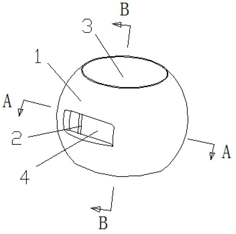
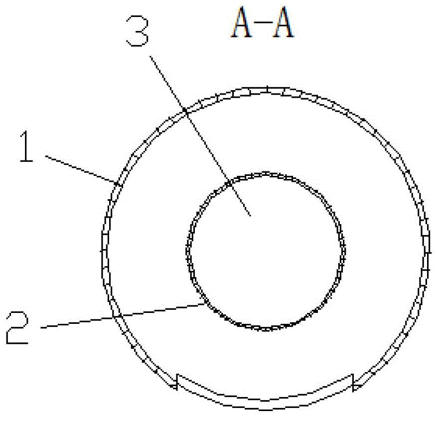
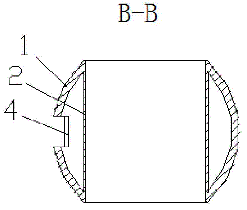
[0024] see Figure 1-Figure 5 As shown, a ball valve spool includes a hollow outer sphere 1 and an inner straight pipe 2. The inside of the outer sphere 1 is provided with a through hole 3, and the cross-sectional shape of the upper and lower ends of the through hole 3 is They are mutually parallel and equal circles, and the outer sphere 1 is provided with a notch 4 that runs through the inside and outside of the outer sphere; the inner straight tube 2 is fitted into the through hole 3 of the outer sphere 1 and the junction is tight fit.

[0025] Further, the above-mentioned inner straight pipe 2 and the through hole 3 of the outer spherical body 1 are transition fit.

...


PUM


Abstract

The invention provides a ball valve core and belongs to the valve technical field. The ball valve core solves the technical problems that the ball valve core is poor in sealing performance, short in service life and high in factory cost in the existing market. The ball valve comprises a hollow outer ball body and an inner straight pipe, wherein a through hole is formed in the interior of outer ball body, cross sections of the upper end and the lower end of the through hole are mutually parallel and equal circles, a notch which penetrates through inside and outside the outer ball body is formed in the outer ball body, and the inner straight pipe is embedded in the through hole of the outer ball body and joint part of the inner straight pipe and the through hole of the outer ball body is tightly abutted. A production method of the ball valve core comprises the following steps: prefabricating the outer ball body and the inner straight pipe; assembling the outer ball body and the inner straight pipe; chipping off the end portion, exposed to the outer ball body, of the inner straight pipe; opening the notch in a big circle of the outer ball body; and conducting polishing treatment on an assembled blank. The ball valve core and the production method of the ball valve are good in sealing performance and long in service life, and lower factory cost of products.

Description

technical field [0001] The invention relates to a valve, in particular to a ball valve core and a production method thereof. Background technique [0002] As we all know, the structure and defects of the current ball valve spool are: first, the bottom of the notch opened on the outer sphere is closed, resulting in waste of materials and increased material costs; second, the connection between the outer sphere and the inner straight pipe is through Welding molding requires chamfering, poor sealing performance, and short service life; third, one end of the inner straight pipe needs to be flanged and fixed on the outer sphere; the second and third points have cumbersome procedures, which directly lead to low work efficiency and increased factory costs. [0003] The current production process of the ball valve core needs to use stamping equipment. The inner straight tube needs to be bored with the inner hole, and the outer sphere is made of a straight tube by expansion technolog...

Claims


Application Information

Patent Timeline
Patent Type & Authority Patents(China)
IPC IPC(8): F16K5/08F16K5/06B23P15/00
Inventor 杨建国
Owner 杨建国
Learn More