Flow control valve for test of electric submersible centrifugal oil pump units

A technology for flow control valves and centrifugal pumps, which is applied in the direction of engine components, valve details, valve devices, etc., can solve the problems of difficult flow control, economic loss, and affecting the performance of electric submersible centrifugal pump units, etc., to achieve slow rotation speed and high flow rate Easy and accurate control

Active Publication Date: 2013-05-22
CHINA PETROLEUM & CHEM CORP +1
View PDF8 Cites 3 Cited by
  • Summary
  • Abstract
  • Description
  • Claims
  • Application Information

AI Technical Summary

Problems solved by technology

When the existing flow control valve adjusts the flow pressure, as the pressure continues to increase, the flow is difficult to control, the test data is unstable, and the deviation is large, which affects the accurate judgment of the performance of the electric submersible centrifugal pump unit, and cannot guarantee the electric submersible pump. The factory quality of the centrifugal pump unit, there are unqualified electric submersible centrifugal pump units for production, which will cause major economic losses to the oil production of the oil field

Method used


Image

  • Flow control valve for test of electric submersible centrifugal oil pump units

Examples


Embodiment Construction

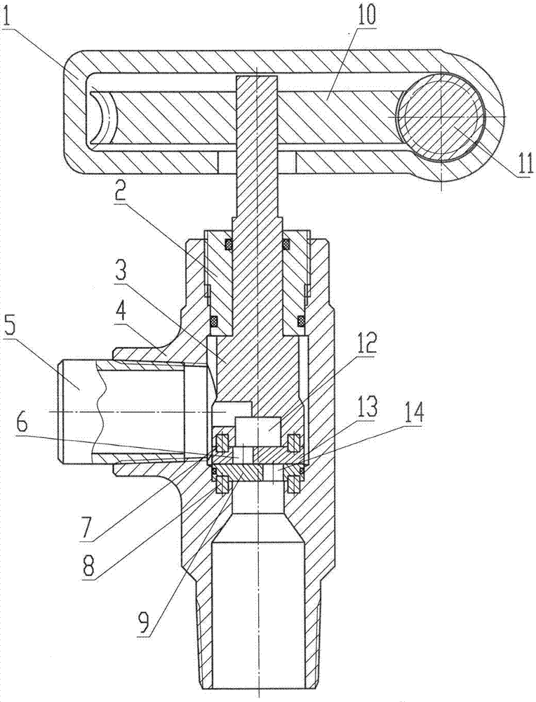
[0007] Embodiments of the present invention will be described below in conjunction with the accompanying drawings.

[0008] As can be seen from the figure, the embodiment of the present invention includes a wheel housing 1, a sealing pressure piece 2, a flow regulating rod 3, a valve body 4, a connecting pipe 5, a connecting shaft 7, a positioning shaft 8, a lower valve plate 9, a turbine 10, and a worm rod 11. The upper valve plate 13 and the positioning shaft 8 position the lower valve plate 9 at the bottom of the inner hole of the valve body 4, so that the lower valve plate 9 cannot rotate, and the outer circumference of the lower valve plate 9 is sealed with the valve body 4, which is realized by a sealing ring. The upper valve plate 13 is press-fitted on the lower valve plate 9, the upper valve plate 13 is fixed on the lower end surface of the flow regulating rod 3 by the connecting shaft 7, the outer thread of the sealing pressing part 2 is connected with the inner thread...


PUM


Abstract

A flow control valve for test of electric submersible centrifugal oil pump units comprises a wheel casing, a sealing press part, a flow adjusting lever, a valve body, a connecting pipe, a connecting haft, a positioning shaft, a lower valve plate, a worm wheel, a worm and an upper valve plate. The upper valve plate and the lower valve plate can generate press force. When an upper eccentric hole and a lower eccentric hole are not communicated, a runner can be closed. Communicated channels of the upper eccentric hole and the lower eccentric hole can be adjusted by rotating the flow adjusting lever, so that flow can be adjusted. Rotation of the flow adjusting lever is controlled by the worm wheel and the worm, and is low in speed and laborsaving, so that flow is convenient and accurate to control and stable, test data are real and reliable, performance of the electric submersible centrifugal oil pump units can be accurately judged, delivered electric submersible centrifugal oil pump units are guaranteed to be qualified, and the flow control valve has remarkable economic benefits.

Description

technical field [0001] The invention is the equipment used for the test of the electric submersible centrifugal pump in the oil field, and is a flow control valve for the test of the electric submersible centrifugal pump unit. Background technique [0002] Before the electric submersible centrifugal pump unit leaves the factory, its performance must be tested in a simulated state. When testing it, a flow control valve should be used. The function of the flow control valve is that when the electric submersible centrifugal pump unit operates normally for 30 minutes When entering a stable state, open or close the flow control valve to adjust each measuring point, measure the pump displacement, head, motor voltage, current, power, speed and other parameters at different measuring points through the computer and draw the characteristic curve, through the data The test results are obtained, which provide accurate and reliable basis for the quality of the electric submersible centr...

Claims


Application Information

Patent Timeline
Patent Type & Authority Applications(China)
IPC IPC(8): F16K17/20F16K31/53
Inventor 高国强谢文献王欣辉满德金李永强巩同宇王锦程许建华张莹简纪新曾建川陈宁高国栋张晶
Owner CHINA PETROLEUM & CHEM CORP
Why Eureka
Try Eureka