Quality detection device for embossing printed matter

A detection device and printed matter technology, applied in measuring devices, material analysis through optical means, instruments, etc., can solve the problems of low detection efficiency, cumbersome operation, camera shaking, etc., and achieve comprehensive image acquisition, simple structure, and ingenious conception Effect

Inactive Publication Date: 2019-11-15
CHANGSHA NORMAL UNIV
View PDF0 Cites 1 Cited by
  • Summary
  • Abstract
  • Description
  • Claims
  • Application Information

AI Technical Summary

Problems solved by technology

[0002] The existing quality inspection device for printed matter mainly includes a camera, a light box and a camera clamping mechanism. The existing quality inspection device for printed matter allows the camera to move up and down to adjust the shooting distance. Since the camera moves up and down, it is easy to shake the camera, resulting in poor shooting effect, and Since the angle between the printed matter and the camera needs to be manually adjusted continuously, the detection efficiency is low, and the irradiation direction of the lamp is fixed. It is necessary to manually rotate the printed matter to collect pictures under different lamp irradiation directions. The operation is cumbersome and the lamp cannot be changed. The angle of illumination of the tube makes it impossible to capture a more comprehensive picture of the concave-convex surface of the print

Method used


Image

  • Quality detection device for embossing printed matter
  • Quality detection device for embossing printed matter

Examples


Embodiment Construction

[0014] In order to make the purpose, technical solutions and advantages of the embodiments of the present invention clearer, the technical solutions in the embodiments of the present invention will be clearly and completely described below in conjunction with the drawings in the embodiments of the present invention. Obviously, the described embodiments It is a part of embodiments of the present invention, but not all embodiments. Based on the embodiments of the present invention, all other embodiments obtained by persons of ordinary skill in the art without creative efforts fall within the protection scope of the present invention.

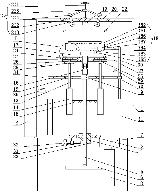
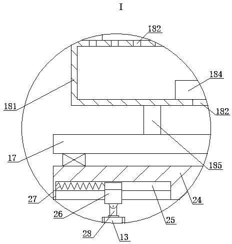
[0015]A quality inspection device for concave-convex printed matter, as shown in the figure, includes a box body 1, a box door 2 is provided at the front opening of the box body 1, a through hole 3 is opened in the middle of the bottom side of the box body 1, and a There is a screw nut 4, the internal thread of the screw nut 4 is installed with a ...


PUM


Abstract

The invention relates to a quality detection device for an embossing printed matter. The quality detection device comprises a box body, wherein a box door is arranged at a front side opening of the box body, a through hole is opened in the middle of the bottom side of the box body, a nut is arranged in the through hole, a lead screw is arranged in the nut in a threaded manner, a first gear is fixedly mounted on the lower end of the lead screw, a motor is fixedly mounted on one side of the bottom side of the box body, a coaxial gear column is fixedly mounted on the lower end of a motor rotatingshaft, the first gear meshes with the gear column, an upper end bearing of the periphery of the lead screw is provided with a coaxial fixing ring, the left side and the right side of the fixing ringare separately provided with horizontal plates, the outer side of the bottom side of each horizontal plate is fixedly connected to the upper end of a telescopic rod, respectively, and the lower end ofeach telescopic rod is fixedly connected with the bottom of the box body respectively. The device of the invention has the advantages of simple structure and ingenious design, and realizes the lifting and lowering adjustment of the printed matter, the change of angles between the top side of the printed matter and the horizontal plane, and the slow rotation of the printed matter by one motor; andthe lifting and lowering of the printed matter can change the distance between the printed matter and a camera.

Description

technical field [0001] The invention belongs to the field of quality detection devices for printed matter, in particular to a quality detection device for concave-convex printed matter. Background technique [0002] The existing quality inspection device for printed matter mainly includes a camera, a light box and a camera clamping mechanism. The existing quality inspection device for printed matter allows the camera to move up and down to adjust the shooting distance. Since the camera moves up and down, it is easy to shake the camera, resulting in poor shooting effect, and Since the angle between the printed matter and the camera needs to be manually adjusted continuously, the detection efficiency is low, and the irradiation direction of the lamp is fixed. It is necessary to manually rotate the printed matter to collect pictures under different lamp irradiation directions. The operation is cumbersome and the lamp cannot be changed. Due to the angle of illumination of the tu...

Claims


Application Information

Patent Timeline
Patent Type & Authority Applications(China)
IPC IPC(8): G01N21/84G01N21/01
CPCG01N21/01G01N21/84G01N2021/0112
Inventor 王章苹
Owner CHANGSHA NORMAL UNIV
Why Eureka
Try Eureka