Double-spindle machine tool

a machine tool and double-spindle technology, applied in the direction of metal-working holders, large fixed members, supporters, etc., can solve the problems of inability to align the spindles and the inability to keep the distance between the axes of rotation of the tool-holder spindles accurately

Inactive Publication Date: 2006-08-17
CROSS HULLER
View PDF11 Cites 16 Cited by
  • Summary
  • Abstract
  • Description
  • Claims
  • Application Information

AI Technical Summary

Benefits of technology

[0005] It is an object of the invention that changes in distance of the axes of rotation of the tool-holder spindles can be compensated by comparatively simple means even during operation of the machine.

Problems solved by technology

A fundamental problem with these double-spindle machine tools resides in that the distance between the axes of rotation of the tool-holder spindles cannot be kept accurately.
On the one hand this is due to the fact that the spindles cannot be aligned one in relation to the other with absolute accuracy.

Method used


Image

  • Double-spindle machine tool
  • Double-spindle machine tool
  • Double-spindle machine tool

Examples


Embodiment Construction

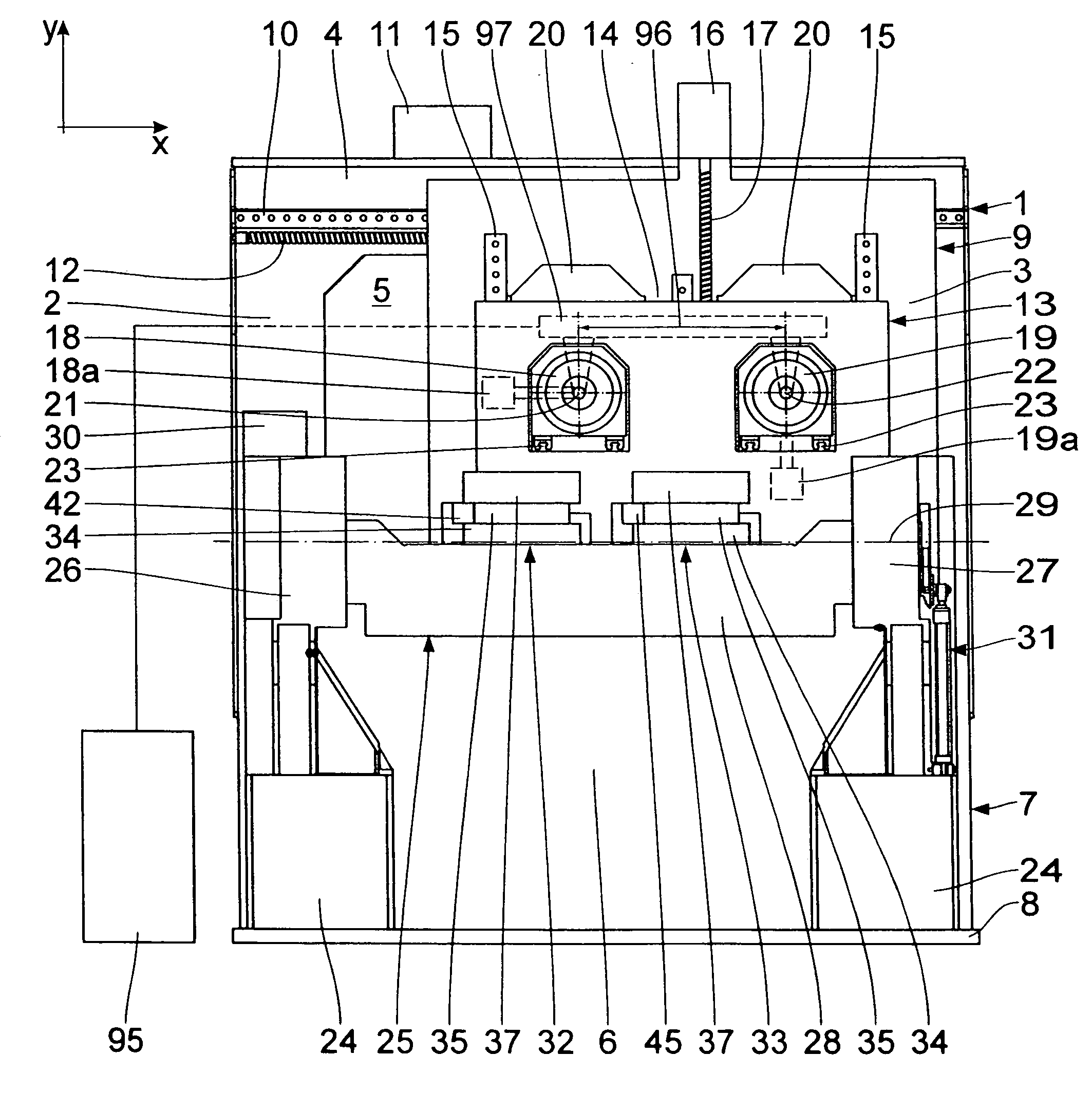
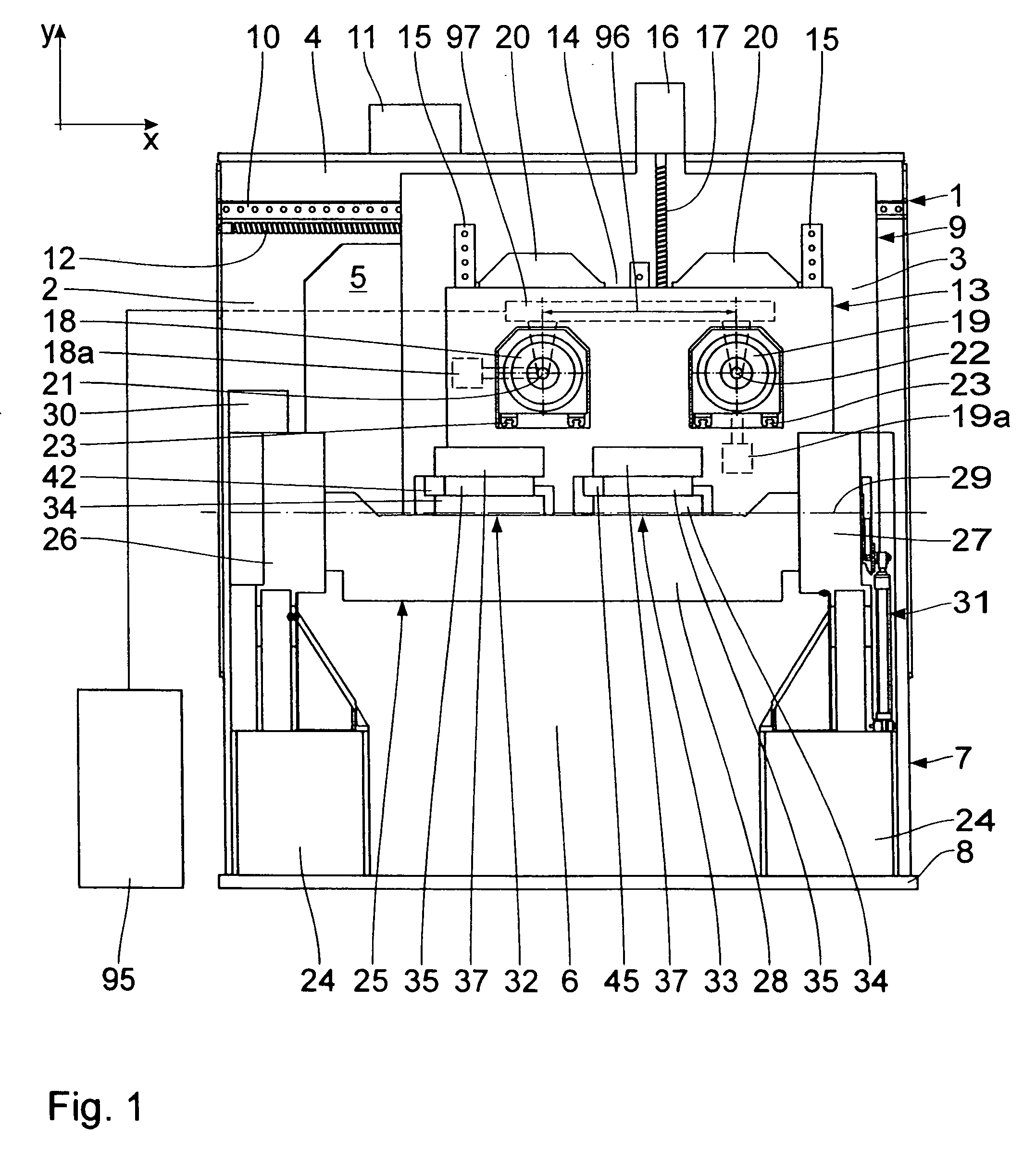
[0017] The machine tool seen in FIG. 1 is a double-spindle machine tool with a rectangular frame 1 configured by vertical side props 2, 3 which extend in a y direction, and a horizontal, top crossbeam 4 and a bottom crossbeam (not shown) each of which extending in an x direction and uniting the side props 2, 3. The side props 2, 3 and the crossbeams 4 envelop an interior 5 which is open bilaterally, in particular towards the working area 6. The frame 1 supports itself via a subframe 7 on a foundation plate 8.

[0018] On the front end, turned towards the working area 6, of the frame 1, provision is made for an equally frame-type x skid 9 which is displaceable in the x direction. To this end, an x guide rail 10 is mounted on each crossbeam 4, with the x skid 9 being guided thereon. Actuation of the x skid 9 takes place by an x motor 11 by way of an x ball screw 12 which extends in the x direction and is housed against rotation in the side props 2, 3 of the frame 1.

[0019] Guided on the...


PUM

PropertyMeasurementUnit
radiusaaaaaaaaaa
radiusaaaaaaaaaa
distanceaaaaaaaaaa

Abstract

A double-spindle machine tool comprises two tool-holder spindles and two work holding fixtures allocated thereto. A work holding fixture comprises a work carrier plate which supports itself on an adjustable abutment. This abutment is adjusted by means of an adjusting device in dependence on changes in the distance of the axes of rotation of the tool-holder spindles.

Description

BACKGROUND OF THE INVENTION [0001] 1. Field of the Invention [0002] The invention relates to a double-spindle machine tool, comprising a frame; two tool-holder spindles, which have parallel axes of rotation that are disposed at a distance from one another; two work holding fixtures for accommodation of a respective work; devices for displacement of the works relative to the tool-holder spindles. [0003] 2. Background Art [0004] Double-spindle machine tools are generally known, for example from WO 2004 / 067223 A1. A fundamental problem with these double-spindle machine tools resides in that the distance between the axes of rotation of the tool-holder spindles cannot be kept accurately. On the one hand this is due to the fact that the spindles cannot be aligned one in relation to the other with absolute accuracy. On the other hand this is rather substantially caused by the fact that the distance of the tool-holder spindles changes under the action of numerous temperature influences for ...

Claims


Application Information

Patent Timeline
Patent Type & Authority Applications(United States)
IPC IPC(8): B23B39/16
CPCB23Q1/282B23Q3/18B23Q11/0007B23Q2230/002B23Q2039/002Y10T408/3806Y10T409/307784Y10T408/5617Y10T409/305824Y10T408/175Y10T408/385
Inventor HILLINGER, ALFREDBRUDER, HUBERT
Owner CROSS HULLER
Why Eureka
Try Eureka