Aggregate angularity on-site real-time monitoring device

A real-time monitoring and aggregate technology, applied to the analysis of materials, instruments, etc., can solve the problems of low efficiency, inability to detect the angular state of aggregates in real time, and large labor load, and achieve the effect of expanding the scope of application

Active Publication Date: 2022-01-14
CHANGAN UNIV
View PDF26 Cites 1 Cited by
  • Summary
  • Abstract
  • Description
  • Claims
  • Application Information

AI Technical Summary

Problems solved by technology

[0003] At present, most of the aggregate detection methods on the market are to collect the aggregate, bring it to the experimental equipment, and then detect the angularity of the aggregate through a certain detection method. This method requires the detection personnel to run back and forth, and cannot be real-time. Detecting the angular state of aggregates is inefficient and labor-intensive

Method used


Image

  • Aggregate angularity on-site real-time monitoring device
  • Aggregate angularity on-site real-time monitoring device
  • Aggregate angularity on-site real-time monitoring device

Examples


Embodiment

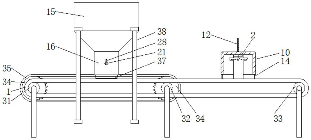
[0039] Such as figure 1 The on-site real-time monitoring device for the angularity of aggregates shown includes a conveyor belt 1 for conveying aggregates, a fixed bracket for installing the conveyor belt 1, a set of rotating rollers installed on the bracket and driving the conveyor belt 1 to rotate, and the conveyor belt 1. Directly above, there is a distributing mechanism erected on both sides of the fixed support that can evenly and stably distribute the aggregate on the conveyor belt 1, and the fixed support is equipped with an image acquisition mechanism 2 that takes pictures of the dispersed aggregate, and the image acquisition Mechanism 2 is provided with a covering mechanism for shading aggregates during shooting, and a detection mechanism 4 for testing materials after photographing is provided under the forward end of conveyor belt 1, and a detection mechanism 4 for testing aggregates after photographing is provided under the forward end of conveyor belt 1. Undertake ...


PUM


Abstract

The invention discloses an aggregate angularity on-site real-time monitoring device, and belongs to the technical field of aggregate angularity detection. A material distribution mechanism which is erected on two sides of a fixed bracket and can uniformly and stably distribute aggregate on a conveying belt is arranged right above the conveying belt; an image acquisition mechanism for shooting the dispersed aggregate is mounted on the fixed bracket; a covering mechanism for shading the shot aggregate is arranged on the image acquisition mechanism; a detection mechanism for testing the shot material is arranged under the advancing tail end of the conveying belt; and a sampling mechanism for receiving the shot aggregate and conveying the shot aggregate to the inner side of the detection mechanism is arranged under the advancing tail end of the conveying belt. Through continuous rotation of the discharging roller, aggregate in each notch is released to the upper end face of the conveying belt at a certain distance in a spaced manner, so that the aggregate is uniformly and independently distributed on the conveying belt, and favorable conditions are provided for subsequent photographing of the aggregate by the image acquisition mechanism.

Description

technical field [0001] The invention relates to the technical field of aggregate angularity detection, in particular to an on-site real-time monitoring device for aggregate angularity. Background technique [0002] Aggregate is also called aggregate, which is mainly divided into coarse aggregate and fine aggregate. Aggregate is one of the main materials of concrete and plays the role of skeleton in concrete. The angularity and roughness of aggregate will affect the mixing Therefore, the roughness of the aggregate needs to be tested before the use of the aggregate, that is, the angular performance of the aggregate should be tested. [0003] At present, most of the aggregate detection methods on the market are to collect the aggregate, bring it to the experimental equipment, and then detect the angularity of the aggregate through a certain detection method. This method requires the detection personnel to run back and forth, and cannot be real-time. Detecting the angular state...

Claims


Application Information

Patent Timeline
Patent Type & Authority Applications(China)
IPC IPC(8): G01N15/00
CPCG01N15/00Y02W30/91
Inventor 汪海年王惠敏刘胜兰冯珀楠张琛焦虎李元乐雷鸣宇许卉杨一
Owner CHANGAN UNIV
Why Eureka
Try Eureka