Embedded led flat light frame and embedded led flat light
A LED flat lamp, embedded technology, applied in lighting devices, light sources, fixed lighting devices, etc., can solve the problems of high occupation cost, increased number of parts, fixed size, etc., to achieve low occupation cost, delay in use, and easy disassembly Effect
- Summary
- Abstract
- Description
- Claims
- Application Information
AI Technical Summary
Problems solved by technology
Method used
Image
Examples
Embodiment 1
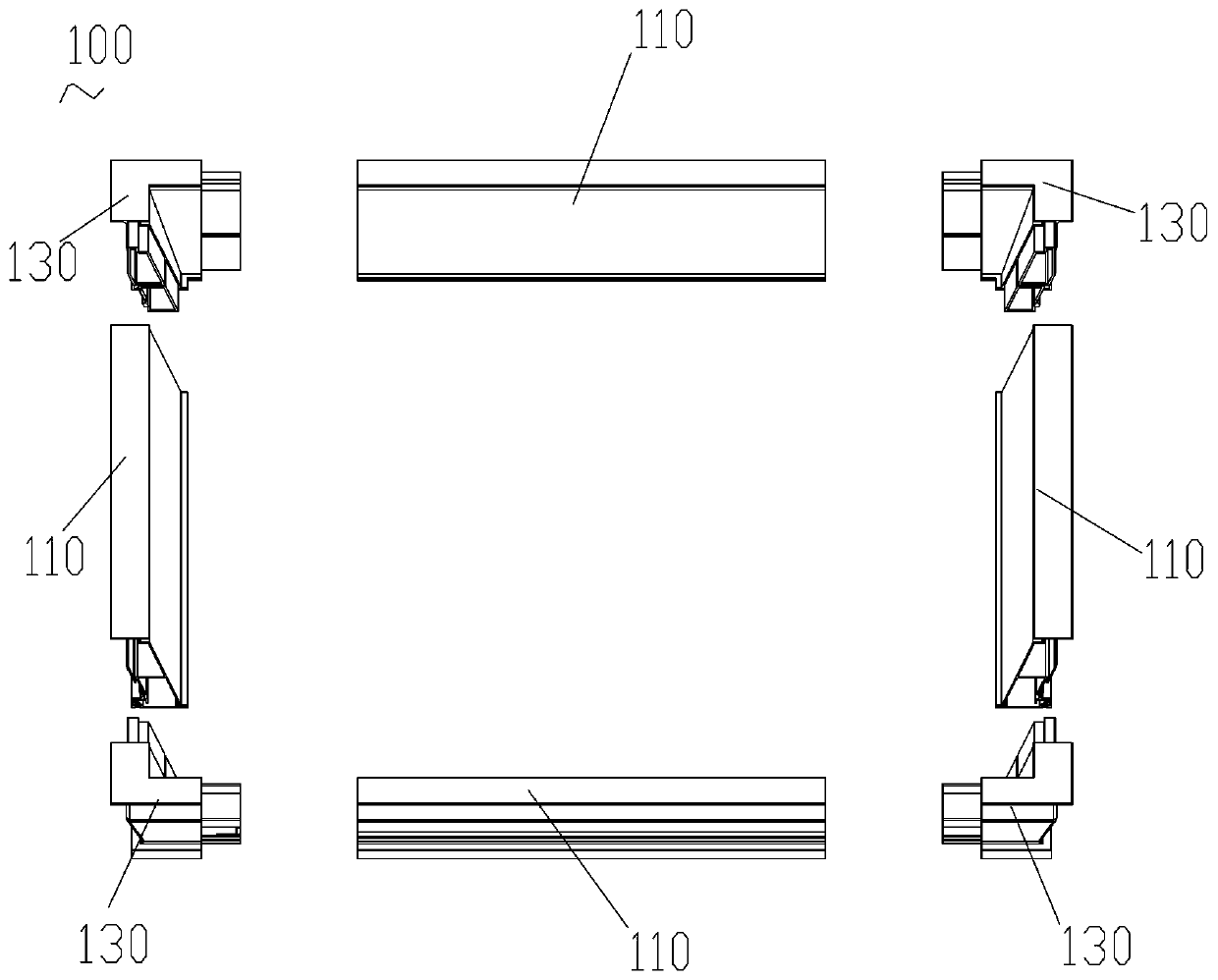
[0043] Such as figure 1 , the light frame 100 of the embedded LED flat light includes four frames 110 and four joints 130 . The four frames 110 are connected by four joints 130 to form a rectangular lamp frame 100 .
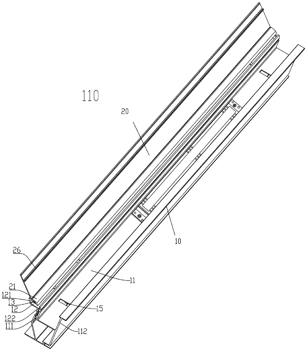
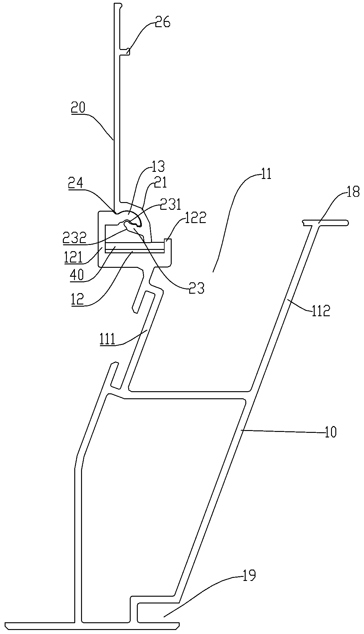
[0044] Such as Figure 2 to Figure 6As shown, the frame 110 includes a frame body 10 and a buckle plate 20 . The pinch plate 20 is rotatably installed on the frame body 10 . The frame body 10 has a first U-shaped groove 11 . The first U-shaped groove 11 includes a first groove wall 111 and a second groove wall 112 . A second U-shaped groove 12 is disposed on the first groove wall 111 . The second U-shaped groove 12 has a third groove wall 121 and a fourth groove wall 122 . The upper end of the third groove wall 121 is provided with a support portion 13 . The pinch plate 20 is provided with a rotating portion 21 . The rotating part 21 is provided with a first locking slot 22 . The first inner wall 221 of the first locking slot 22 is arc-shaped, and the fi...
Embodiment 2
[0052] Such as Figure 7 , Figure 8 and Figure 9 As shown, the embedded LED flat lamp includes the embedded LED flat lamp light frame 100 of Embodiment 1, the lamp board 70 and the PCB board 60 . A plurality of LED lamps 71 are arranged on the lamp board 70 . PCB board 60 edges are embedded in PCB board slot 19 ( image 3 , Figure 4 shown). The edge of the light board 70 is clamped and fixed by the frame body 10 and the gusset plate 20 together. The power supply 50 is provided in the housing 10 . The power supply 50 is electrically connected to the LED lamp 71 through the PCB board 60 .
Embodiment 3
[0054] Such as Figure 10 As shown, the difference between this embodiment and Embodiment 1 is that the elastic return device includes at least a pressure plate 41 and a compression spring 42 instead of the leaf spring 40 in Embodiment 1. The pressing plate 41 is disposed between the compression spring 42 and the rotating part 21 , and the rotating part 20 presses the compression spring 42 through the pressing plate 41 . All the other structures are the same as in Example 1.
PUM
 Abstract
Description
Claims
Application Information
 - R&D
- Intellectual Property
- Life Sciences
- Materials
- Tech Scout
- Unparalleled Data Quality
- Higher Quality Content
- 60% Fewer Hallucinations
Browse by: Latest US Patents, China's latest patents, Technical Efficacy Thesaurus, Application Domain, Technology Topic, Popular Technical Reports.
© 2025 PatSnap. All rights reserved.Legal|Privacy policy|Modern Slavery Act Transparency Statement|Sitemap|About US| Contact US: help@patsnap.com


