
Circuit breaker

A circuit breaker and device body technology, applied in the field of circuit breakers, can solve the problems of false display of the tripping state, increased manufacturing cost, wear of the bulging part, etc., and achieves the effect of preventing false display and simple structure

Active Publication Date: 2013-05-22
PANASONIC INTELLECTUAL PROPERTY MANAGEMENT CO LTD
View PDF5 Cites 6 Cited by
  • Summary
  • Abstract
  • Description
  • Claims
  • Application Information

AI Technical Summary

Problems solved by technology

[0008] However, in the above-mentioned circuit breaker, the slit 26a and the bulging portion 263 are formed in the display panel 260 in order to display the trip of the display member 26, so that the structure of the display panel 260 becomes complicated, and there is a problem that the manufacturing cost becomes high.
In addition, since the bulging portion 263 slides over the restricting protrusion 271 while sliding over the restricting protrusion 271 , at least one of the bulging portion 263 and the restricting protrusion 271 may be abraded.
In this case, the engagement between the protruding portion 263 and the restricting protrusion 271 becomes insufficient, and even in the disconnected state, the display member 26 may rotate to the trip position to perform an erroneous display.
[0009] In addition, since the elastic piece 261 bends during tripping, for example, the elastic piece 261 is deformed due to fatigue, and even in the disconnected state, there is a possibility of false display indicating the tripped state.

Method used


Image

  • Circuit breaker
  • Circuit breaker
  • Circuit breaker

Examples


Embodiment approach )

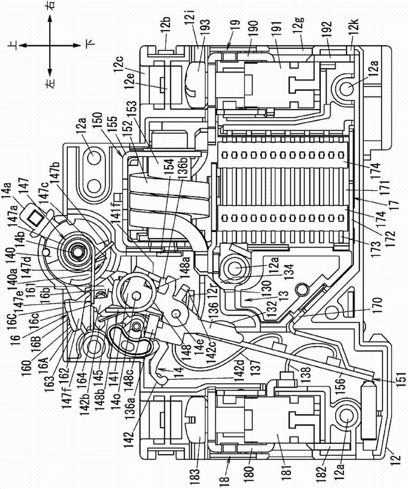
[0033] This embodiment is a circuit breaker that can input, flow, and break current under normal circuit conditions, and can input current, flow for a certain period of time, and then break under certain abnormal circuit conditions such as a short circuit. Below, with figure 1 The up, down, left, and right directions are used as a reference, and the direction perpendicular to the up, down, left, and right directions will be described as the front and rear directions.

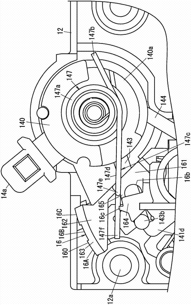
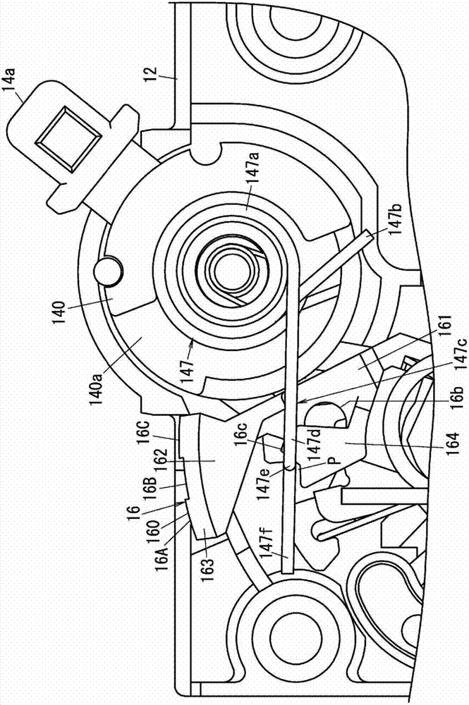
[0034] Such as figure 1 , 4 , 5, the circuit breaker of this embodiment includes: a body 10, which is composed of a first half 11 and a second half 12; a contact mechanism (contact part) 13, which has a fixed contact 130 and a movable contact 132 The handle 140 has an operating handle 14a; the handle spring 147; the link mechanism 14 is configured to turn on and off the electrical connection between the fixed contact 130 and the movable contact 132 via the handle 140; the tripping mechanism (electromagnetic ...


PUM


Abstract

Provided is a circuit breaker that can form a trip display with a simple structure and prevent erroneous display. This circuit breaker is provided with: a device body (10) in which a window hole (11o) is formed; a contact point mechanism (13); a handle (140) that rotates between a closed contact position and an open contact position; a link mechanism (14); a magnetic release means (150) and a thermomotive release means (151) that forcibly open the contact point mechanism (13); a handle spring (147) that impels the handle (140) toward the open contact position; a display member (16) that is supported freely rotatably by the device body (10) and has display parts (16A - 16C); and a latch spring (145) one end of which presses against the display member (16) and impels the display member (16) toward the trip position side where a trip display part (16A) faces the window hole (11o). A latching protrusion (16c) that mates with a latching piece (147e) of the handle spring (147) and regulates the rotation toward the trip position side is formed for the display part (16).

Description

technical field [0001] The present invention relates to circuit breakers. Background technique [0002] Conventionally, there is a circuit breaker that can switch between an open state (a state in which contacts are opened) and a closed state (a state in which contacts are closed) of a contact part by operating a handle. And, in the above circuit breaker there is also Figure 12 circuit breaker as shown, Figure 12 The shown circuit breaker is equipped with a display part 26, and the display part 26 displays whether the contact part is in an open state, a closed state, or a state in which an abnormal current is detected and the contact part is forcibly opened (trip state) (see, for example, Japan Patent Publication No. 2009-212065). [0003] The above-mentioned display part 26 has a display panel 260, which is rotatably installed in the body of the circuit breaker, and is arranged at a position facing an unillustrated window hole formed on the body, and displays the positio...

Claims


Application Information

Patent Timeline
Patent Type & Authority Applications(China)
IPC IPC(8): H01H73/12H01H71/04
CPCH01H71/04
Inventor 水野初男石黑宏文中道义也
Owner PANASONIC INTELLECTUAL PROPERTY MANAGEMENT CO LTD
Learn More