Connection confirming mechanism

A technology of a force mechanism and a matching part, which is applied in the directions of mechanical equipment, pipes/pipe joints/fittings, circuits, etc., can solve the problems of pipe shape limitation, difficulty in visual confirmation, and small exposed area of ​​the tester, so as to prevent errors. Display and suppress the effect of increasing

Inactive Publication Date: 2013-01-02
NIFCO INC
View PDF1 Cites 0 Cited by
  • Summary
  • Abstract
  • Description
  • Claims
  • Application Information

AI Technical Summary

Problems solved by technology

[0004] However, the conventional connection checking mechanism described in the above-mentioned Patent Document 1 has a structure in which the tester pushed by the flange portion of the pipe is exposed to the outside, so the exposed area is determined by the thickness of the flange portion of the pipe. When the flange part is thin, there is a problem that the exposed area of ​​the tester becomes small and it becomes difficult to check visually.
Therefore, in order to secure the exposed area of ​​the tester, the shape of the piping (flange portion) may be limited
[0005] In addition, in the above-mentioned conventional connection confirmation mechanism, when the user inserts the pipe into the connector at an angle by mistake, etc. and pushes the checker in the direction of expansion at the front end of the pipe, there is a possibility that the two may not be connected even though the two are not connected. state, but the checker showing the combined state is pushed and exposed to the outside

Method used


Image

  • Connection confirming mechanism
  • Connection confirming mechanism
  • Connection confirming mechanism

Examples


no. 1 approach

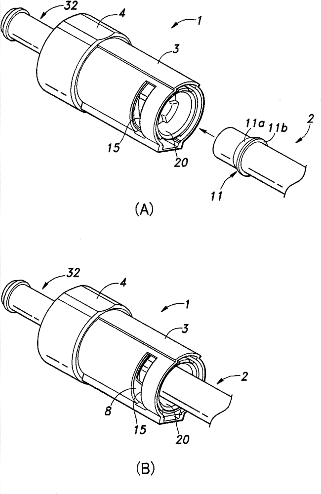
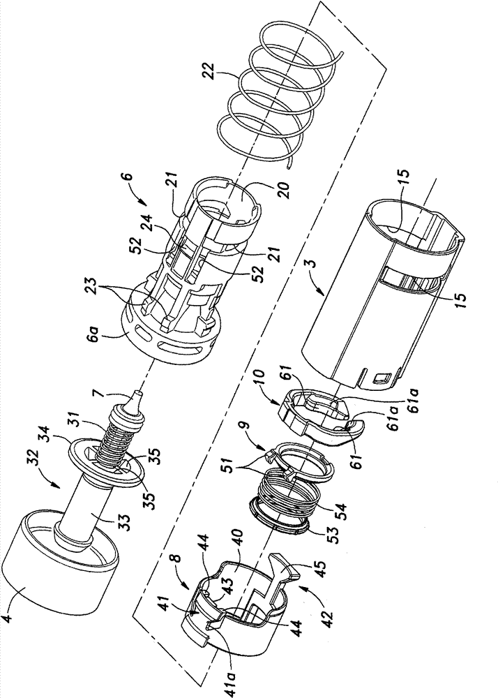
[0033] figure 1 It is a perspective view of a connector equipped with a connection confirmation mechanism according to a first embodiment of the present invention, figure 2 It is an exploded perspective view of the main part of this connector. In the following description, the term "front (front)" indicating direction refers to figure 1 The relative connector 1 of (A) is along the insertion direction (arrow direction) of the axis of the tube 2 , and the term "rear (rear)" means the opposite direction.

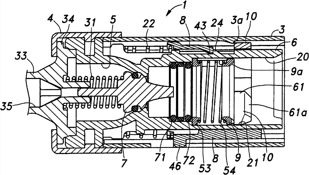
[0034] The connector 1 is a part combined with the pipe 2 for conveying fluid, and its outer shell is composed of a main body cover 3 and an end cover 4, and accommodated inside it: a flow path 5 (refer to image 3 ) housing 6; a valve 7 for opening and closing the flow path 5; a combination display member 8 that displays the state of completion of coupling between the connector 1 and the tube 2 so that the user can visually confirm it; a slide member 9 that slides; and a l...

no. 2 approach

[0056] Figure 12 It is an exploded perspective view of main parts of a connector equipped with a connection confirmation mechanism according to a second embodiment of the present invention, Figure 13 It is an explanatory diagram of the connection confirmation display operation of this connector. Here, the same reference numerals are assigned to the same components as in the first embodiment, and matters not particularly mentioned including components omitted from illustration are the same as in the case of the first embodiment.

[0057] exist Figure 12 in, as figure 2 As an alternative to the slide member 9 and lock member 10 shown, the connector has a new lock member 101 that functions as both. In this case, the combined display part 8 does not have the cutout portion around the locked portion 41 shown in the first embodiment, and does not need the rear locking claw 43 arranged between the two engaging pieces 44, forming A mating piece 144 . The locking part 101 has:...

no. 3 approach

[0060] Figure 14 It is a perspective view seen from the front side and the back side of the connector equipped with the connection confirmation mechanism of the third embodiment of the present invention, Figure 15 is an exploded perspective view of the main part of the connector, Figure 16 It is a perspective view seen from the front side and the back side of the lock member, Figure 17 is an assembled perspective view of the combined display part, sliding part, locking part, and inspection plate in an uncoupled state. Here, the same reference numerals are given to the same components as those in the first embodiment, and the items that are not particularly mentioned are the same as those in the first embodiment.

[0061] In the connector 1 of the third embodiment, the housing 6 serves as the outer shell, and the main body cover 3 and the end cover 4 of the first embodiment are omitted. A display window 15 opening on the rear side is provided on the left and right side w...


PUM


Abstract

[Object] When two components are connected, a connection confirming mechanism is provided, which can carry out a display of a completion of connection state with an easily viewable size and prevent a false display of the completion of connection state. [Means of Solving Problem] A connection confirming mechanism, including a lock component 10 maintaining a completion of connection state of two components and a means, which can visually confirm the above-mentioned completion of connection state, has a structure comprising a pipe 2 including a projection and a connector 1 connected with a pipe. The connector is provided in a state wherein a connecting display component 8 is urged to one side relative to a housing 6, and when the pipe is completed to be fastened and connected with the connector, an urging force is released and the connecting display component moves, so that a visual connecting confirmation can be possible from the connector.

Description

technical field [0001] The present invention relates to a connection confirmation mechanism for visually confirming the completion of the connection when two members are connected. Background technique [0002] As a prior art related to such a connection confirmation mechanism, for example, the following structure is known: in the connection confirmation mechanism used to connect the pipe and the connector, a stopper member for preventing the pipe from coming off from the connector main body is provided. There is an anti-loosening protrusion that cooperates with the flange of the pipe, and when the flange of the pipe is connected, the anti-loosening protrusion is pushed up during the process of passing through the stopper, so that the stopper is expanded, so that it is arranged in the The checker on the front side of the stopper member is pushed and exposed to the outside by the flange portion (for example, refer to Patent Document 1). [0003] Patent Document 1: Japanese U...

Claims


Application Information

Patent Timeline
Patent Type & Authority Patents(China)
IPC IPC(8): F16L37/12
CPCF16L37/084F16L37/12F16L37/0841F16L2201/10Y10T403/20F16L37/08F16L37/28F16L37/38F16L55/00
Inventor 中村高章
Owner NIFCO INC
Why Eureka
Try Eureka