
Indoor electronic mortice door lock with bidirectional locking mechanism

A technology of locking mechanism and internal electronics, applied in the direction of building locks, building structures, non-mechanical transmission-operated locks, etc. Simple structure and reliable mechanical properties

Inactive Publication Date: 2013-05-29
ZHONGSHAN SYRON CO LTD
View PDF5 Cites 3 Cited by
  • Summary
  • Abstract
  • Description
  • Claims
  • Application Information

AI Technical Summary

Problems solved by technology

If you don’t carry it with you, you can only put it at home. It’s not safe to put it too obviously. If you put it not obvious, you can’t find it after a long time. It’s similar to the situation of losing a key! There are also electronic door locks, which can be summarized as follows: First, the body is larger and thicker than mechanical locks! This means that the cost is high and the installation is inconvenient! Second, the battery must be installed in the lock, and there are connections on the front and rear panels
If there is a connection, it is easy to break during installation or the wire ends fall off during use, causing a fault, and the lock will not be able to be used; if you forget to change the battery or do not change the battery for a long time, the door lock circuit will not work, because the mechanical key cannot be found for a long time. Without a mechanical key, you can only face the embarrassing situation of destructive entry!

Method used


Image

  • Indoor electronic mortice door lock with bidirectional locking mechanism
  • Indoor electronic mortice door lock with bidirectional locking mechanism
  • Indoor electronic mortice door lock with bidirectional locking mechanism

Examples


Embodiment Construction

[0020] The preferred embodiments of the present invention will be described below in conjunction with the accompanying drawings. It should be understood that the preferred embodiments described here are only used to illustrate and explain the present invention, and are not intended to limit the present invention.

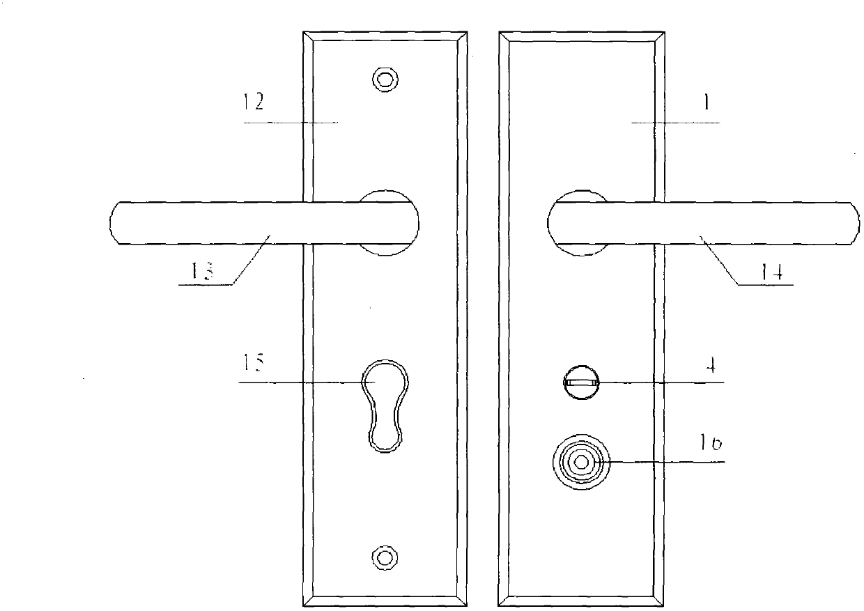
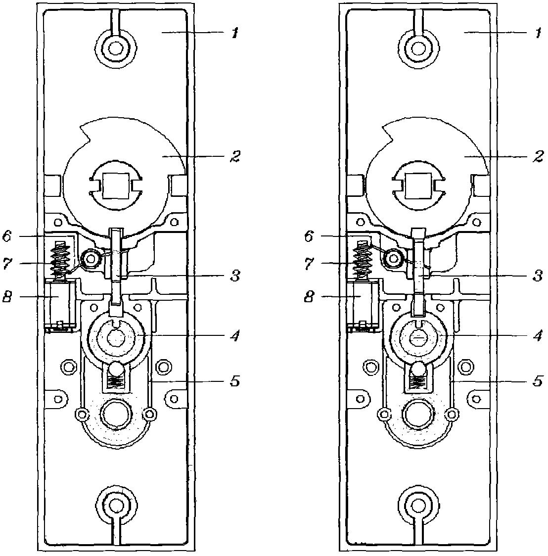
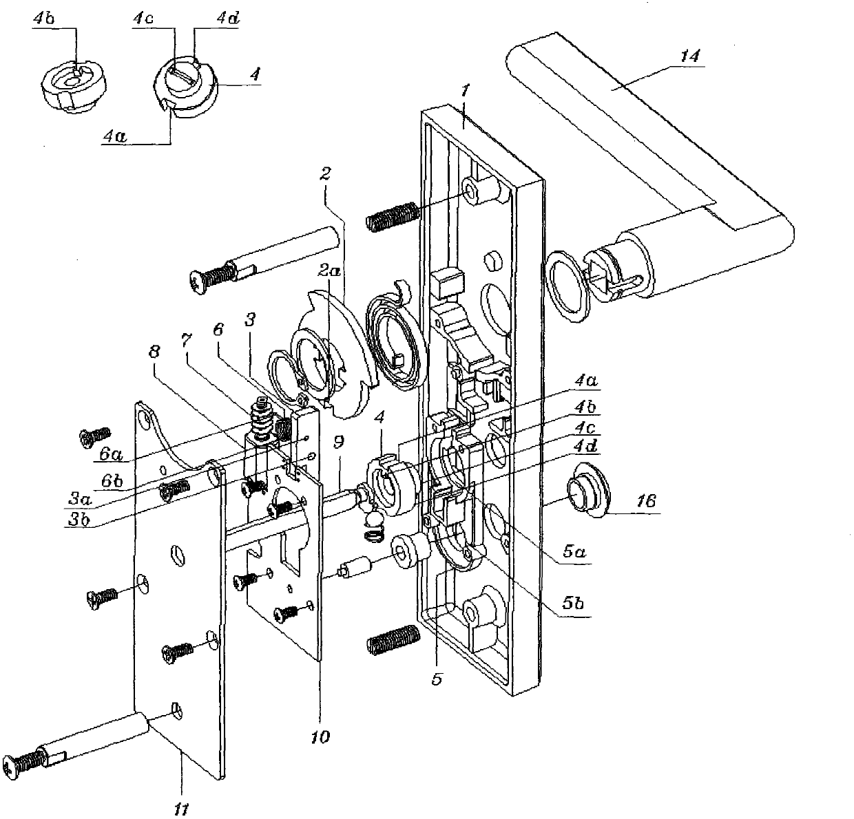
[0021] Such as Figure 1-Figure 5 As shown, an indoor electronic mortise door lock with a two-way locking mechanism, which includes a front panel 1, a handle piece 2, a locking piece 3, an unlocking knob 4, a bracket 5, a driving torsion spring 6, a worm 7, and a micro motor 8 , Tail size piece 9, circuit module 10, front base plate 11, rear panel 12, rear handle 13, front handle 14, rear panel knob 15, contacts 16.

[0022] Both the front panel 1 and the rear panel 12 are cast and formed. The inside of the front panel 1 is provided with guiding and positioning grooves, ribs and columns for the installation and implementation of the two-way locking mechanism. The ou...


PUM


Abstract

The invention discloses an indoor electronic mortice door lock with a bidirectional locking mechanism. The lock comprises a front panel, a rear panel, a front bottom plate and a handle piece, wherein a guide positioning groove, a rib, a column and a worm are arranged between the front panel and the rear panel, the worm is connected with the front panel through a micro motor, the worm is connected with a drive torsional spring connected with a locking piece capable of sliding upwards and downwards, and the locking piece can upwards lock the handle piece and can downwards lock the bidirectional locking mechanism of an unlocking knob. The lock has the advantages of being small in size, simple in process and structure, and reliable in mechanical performance. Batteries are not installed in the front panel or the rear panel, and no connecting lines exist between the front panel and the rear panel. Once the electronic door lock with the bidirectional locking mechanism is installed, the defects that the batteries of a traditional mechanical door lock are out of power and installation is inconvenient due to connecting lines in the front and the back of a common electronic lock are completely avoided, a double-tongue mortice lock body and a single-tongue lock body can be alternatively installed at will, and installation is easy and convenient.

Description

technical field [0001] The invention relates to an indoor electronic mortise door lock, in particular to an indoor electronic mortise door lock with a two-way locking mechanism to realize the locking and opening of the door lock through the operation of an electronic key instead of a mechanical key. Background technique [0002] Among the locking methods of traditional mechanical indoor mortise door locks, one type is: close the door, take out the mechanical key, insert it into the mechanical lock head, and unscrew the square tongue lock door (double tongue lock body); the other type is: close the door When you go to the door, take out the mechanical key, insert it into the mechanical lock head, and turn the knob on the back panel to lock the door (single tongue lock body). And so on, all use mechanical key to lock the door (locking), and the same is true for opening the door (opening), and repeat this operation again. This has disadvantages: First, when the mechanical key ...

Claims


Application Information

Patent Timeline
Patent Type & Authority Applications(China)
IPC IPC(8): E05B47/00
Inventor 汤荣宾
Owner ZHONGSHAN SYRON CO LTD
Learn More