
pneumatic tire

A technology for pneumatic tires and tires, applied in tire parts, tire treads/tread patterns, transportation and packaging, etc., can solve the problems of insufficient pattern rigidity, insufficient wet adhesion performance and slidability, etc. Excellent wet adhesion performance, improved lateral sliding performance, high rigidity effect

Inactive Publication Date: 2016-05-18
SUMITOMO RUBBER IND LTD
View PDF7 Cites 0 Cited by
  • Summary
  • Abstract
  • Description
  • Claims
  • Application Information

AI Technical Summary

Problems solved by technology

However, it cannot be said that the drainage performance is sufficient in the middle rib r2o on the outside of the vehicle assembly, and its wet adhesion performance during cornering and so-called lateral skid performance are not sufficient.
In addition, the rigidity of the pattern is hardly sufficient, and there is still room for improvement in its lateral sliding performance and handling stability.

Method used


Image

  • pneumatic tire
  • pneumatic tire
  • pneumatic tire

Examples


Embodiment

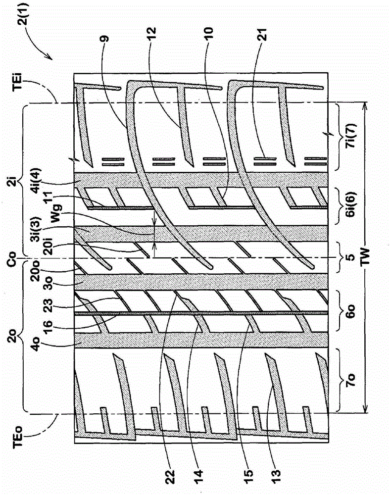
[0059] by figure 1 The tread pattern shown is the basic pattern. According to the specifications in Table 1, a radial tire for passenger cars with a tire size of (225 / 55R17) was trial-produced, and its handling stability and lateral skid performance were tested. In addition, as Comparative Example 1, a Figure 5 The tread pattern shown is the tire.

[0060] The general specifications of each part are as follows.

[0061] Tread contact width TW: 180mm

[0062] Groove width Wg of central main groove: 10mm

[0063] Groove depth Hg of central main groove: 9mm

[0064] Groove width Wg of shoulder main groove: 9mm

[0065] Groove depth Hg of shoulder main groove: 9mm

[0066] Rib width W5 of the center rib: 21mm

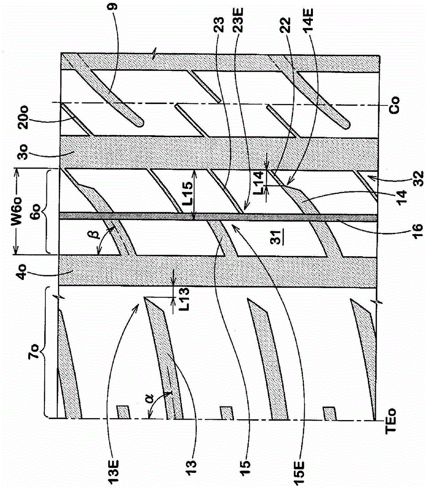
[0067] Rib width W6 of the middle rib: 26mm

[0068] Rib width W7 of the shoulder rib: 36mm

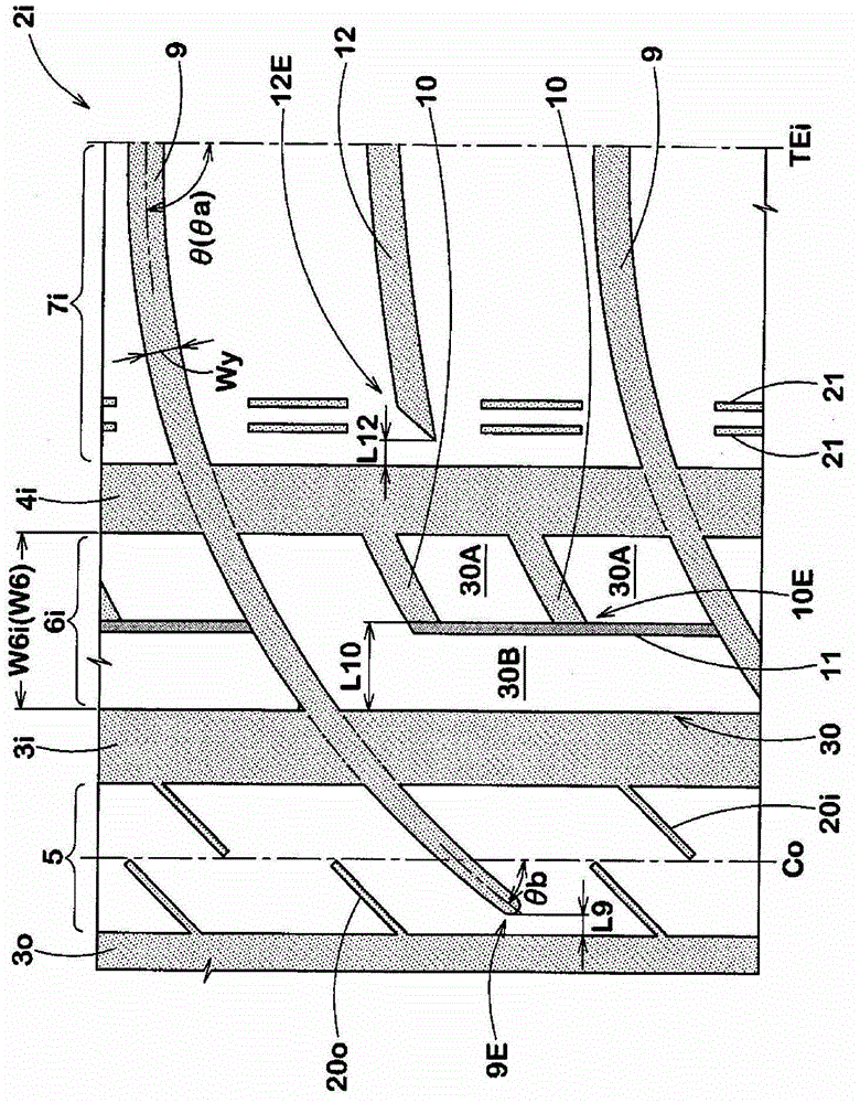
[0069] Groove width Wy of inner inclined transverse main groove: 8mm

[0070] The groove depth Hy of the inner inclined transverse main groove: 7mm

[0071] Groove widt...


PUM


Abstract

A pneumatic tire capable of further improving lateral skid performance and handling stability. It includes an inner inclined lateral main groove extending inward across the tire equatorial plane from a position on the tire axially outer side of a tread contact end on the vehicle mounting inner side and interrupted in the center rib. The shoulder ribs on the inner side are installed on the vehicle, and the inner shoulder lateral grooves extending inward from the tire axially outer side than the tread ground contact end and interrupted in the shoulder ribs are provided between the inner inclined transverse main grooves. . The shoulder rib on the vehicle mounting outer side is provided with an outer shoulder lateral groove extending inward from a position on the outer side in the tire axial direction than the tread edge and interrupted in the shoulder rib. The middle rib on the outside of the vehicle assembly is provided with an outer middle lateral groove and an outer middle lateral auxiliary groove extending from the shoulder main groove toward the tire axially inner side and interrupted in the middle rib. The total number of lateral intermediate lateral grooves formed is less than that of the medial intermediate lateral grooves.

Description

technical field [0001] The present invention relates to a pneumatic tire capable of suppressing the reduction of wet adhesion performance and improving the steering stability performance. Background technique [0002] As a pneumatic tire capable of suppressing a decrease in wet adhesion performance and improving handling stability, there are known, for example, Figure 5 A tire with the tread pattern shown (see Patent Document 1.). [0003] With this tire, the tread portion is divided into a center rib r1, middle ribs r2, r2, and shoulder ribs r3, r3 these 5 ribs. In addition, a plurality of curved inclined grooves y1 are formed on the central rib r1. The curved inclined grooves y1 are located at positions where the central main groove ai on the vehicle mounting inner side crosses the tire equatorial plane Co, and do not reach the central main groove ao on the vehicle mounting outer side. The direction is changed, and the tire equatorial plane Co is interrupted at a positi...

Claims


Application Information

Patent Timeline
Patent Type & Authority Patents(China)
IPC IPC(8): B60C11/04
CPCB60C11/0304B60C2011/0388B60C11/033B60C2011/0341B60C2011/0383B60C2011/1254B60C2011/0381B60C2011/0372B60C2011/0395B60C11/01B60C11/03B60C11/13
Inventor 高木启治
Owner SUMITOMO RUBBER IND LTD
Learn More