Hydraulic braking device and automobile with the same

A hydraulic braking and braking technology, applied in the direction of braking transmission, brakes, vehicle components, etc., can solve problems such as failure to achieve boosting effect, poor braking effect, traffic accidents, etc., and achieve sensitive braking response and structural design. Reasonable and easy to install

Inactive Publication Date: 2013-06-05
BEIQI FOTON MOTOR CO LTD
View PDF4 Cites 0 Cited by
  • Summary
  • Abstract
  • Description
  • Claims
  • Application Information

AI Technical Summary

Problems solved by technology

[0003] The current commercial vehicles with hydraulic disc brakes, such as heavy transport vehicles, large cranes, excavators, bulldozers, road rollers, loading vehicles, electric emergency repair vehicles, engineering emergency vehicles, off-road engineering vehicles, electric welding engineering vehicles, armored engineering vehicles (combat engineering Vehicles) and oxidant sewage treatment engineering vehicles, etc., the braking system generally needs to use a large braking force to achieve braking, and in use, the pedals feel heavy and the braking response is lagging. inconvenience caused by personnel
[0004] At present, the commonly used method is to increase the vacuum booster to improve the boosting performance. However, due to the small space in the cab of the existing hydraulic disc brake commercial vehicles, it is difficult to arrange a larger size in the braking device due to the space limitation of the cab. Vacuum booster, so that the boosting effect cannot be achieved, which will eventually lead to poor braking effect, and emergency situations will also lead to traffic accidents

Method used


Image

  • Hydraulic braking device and automobile with the same
  • Hydraulic braking device and automobile with the same
  • Hydraulic braking device and automobile with the same

Examples


Embodiment 1

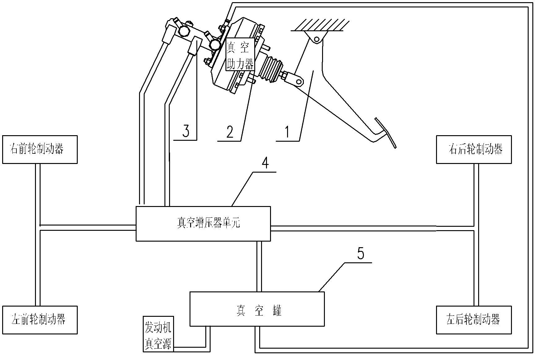
[0029] In the present embodiment, the vacuum booster unit 4 includes at least one vacuum booster, preferably one, which are connected in series through hydraulic pipelines to form a vacuum booster group; the vacuum booster group The vacuum booster at one end is connected to the brake master cylinder 3 through a hydraulic pipeline, and the vacuum booster at the other end of the vacuum booster group is respectively connected to the left front wheel brake, right front wheel brake, left rear wheel brake and right brake. The rear wheel brakes are connected, and each vacuum booster in the vacuum booster group is respectively connected with the vacuum tank 5 through a vacuum pipeline.

[0030] When the vacuum booster group includes a vacuum booster, the vacuum booster at one end of the vacuum booster group and the vacuum booster at the other end of the vacuum booster group are the same vacuum Supercharger.

[0031] Applying the hydraulic braking device described in this embodiment, ...

Embodiment 2

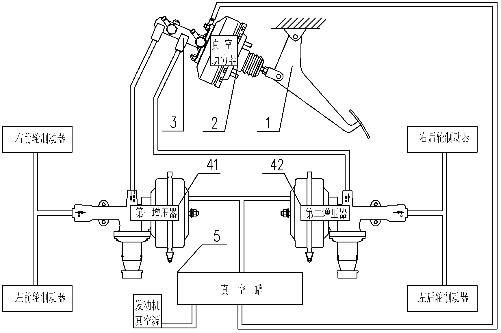
[0033]In this embodiment, the vacuum booster unit 4 includes at least one vacuum booster, preferably two, which are divided into two groups, and the vacuum boosters in each group are connected in series through hydraulic pipelines; wherein, The vacuum booster at one end of the first vacuum booster group is connected to the brake master cylinder 3 through a hydraulic pipeline, and the vacuum boosters at the other end of the first vacuum booster group are respectively connected to the left front wheel brake and the right front wheel brake. The vacuum booster at one end of the second vacuum booster group is connected to the brake master cylinder 3 through a hydraulic pipeline, and the vacuum booster at the other end of the second vacuum booster group is connected to the left rear wheel brake and the right rear wheel brake respectively. The rear wheel brakes are connected, and each vacuum booster in the first vacuum booster group and the second vacuum booster group is respectively ...

Embodiment 3

[0040] This embodiment is basically the same as Embodiment 2, the only difference is that the vacuum booster at one end of the first vacuum booster group is connected to the brake master cylinder 3 through a hydraulic pipeline, and the first vacuum booster group The vacuum booster at the other end is connected with the left front wheel brake and the right rear wheel brake respectively; the vacuum booster at one end of the second vacuum booster group is connected with the brake master cylinder 3 through a hydraulic pipeline, and the The vacuum boosters at the other end of the second vacuum booster group are respectively connected with the left rear wheel brake and the right front wheel brake.


PUM


Abstract

The invention discloses a hydraulic braking device and an automobile with the hydraulic braking device, and relates to the technical field of hydraulic braking. The hydraulic braking device comprises a footstep, a vacuum booster, a braking master pump, a vacuum supercharger unit and a vacuum tank, wherein the footstep, the vacuum booster and the braking master pump are sequentially connected, the vacuum supercharger unit is connected with the braking master pump, a left front wheel brake, a right front wheel brake, a left rear wheel brake and a right rear wheel brake through hydraulic pipelines, and the vacuum tank is connected with an engine vacuum source, the vacuum booster and the vacuum supercharger unit through vacuum pipelines. The hydraulic braking device solves the problem that a hydraulic disc brake motorcycle type is difficult in booster arrangement due to limited cab space and poor in braking force due to an poor boosting effect, according to the fact that the booster and the supercharger unit are used in a combined mode, a set of boosting system is combined, the effect that a braking system obtains enough assistant power is achieved, when the hydraulic braking device is in use, the footstep is light in feeling, and braking is sensitive in reaction.

Description

technical field [0001] The invention relates to the technical field of hydraulic braking, in particular to a hydraulic braking device and an automobile with the hydraulic braking device. Background technique [0002] The vacuum booster is a device that can effectively reduce the braking force, such as figure 1 As shown, the existing hydraulic braking device using a vacuum booster includes a pedal 1, a vacuum booster 2 and a brake master cylinder 3 connected in sequence; an engine vacuum source (vacuum pump) that provides a vacuum source for the vacuum booster 2 or intake manifold); the left front wheel brake, the right front wheel brake, the left rear wheel brake and the right rear wheel brake that are connected to the brake master cylinder 3 through the hydraulic pipeline. Its working process is as follows: stepping on the pedal 1 by manpower provides the initial input force for the vacuum booster 2 assembled in the cab, the engine vacuum source provides the vacuum source ...

Claims


Application Information

Patent Timeline
IPC IPC(8): B60T13/60B60T13/52
Inventor 梁勋乾吴梅江陈乐乾辛国强韩磊李玉龙车培平
Owner BEIQI FOTON MOTOR CO LTD
Why Eureka
Try Eureka