Spectacle frame with spring hinge mechanism

A technology for spring hinges and spectacle frames, which is applied in the directions of glasses/goggles, optics, instruments, etc., can solve the problems of difficult assembly, high processing cost, large volume of the spring hinge mechanism, etc., and achieves easy assembly, simple processing, and compact structure. Effect

Inactive Publication Date: 2011-09-07
朱裕前
View PDF2 Cites 0 Cited by
  • Summary
  • Abstract
  • Description
  • Claims
  • Application Information

AI Technical Summary

Problems solved by technology

[0003] Spectacle frames with a spring hinge mechanism in the prior art include a spectacle frame, studs fixed on both sides of the spectacle frame, two spectacle legs, and a spring hinge mechanism connecting the studs and spectacle legs; "Elastic hinge for glasses" Chinese invention patent, its application number: 200610084093.6, its publication number: CN1869764A, publication date: November 29, 2006, the spring hinge mechanism includes the second joint body welded on the pile head and The box body welded on the temple, and the first joint assembly main body and the spring arranged in the box body, the spring alone ensures that the box body can move on the first joint assembly main body, and the spring alone ensures that the box body is in contact with the second joint assembly body. The main body of the first joint component will not be separated. The spring generally adopts a leaf spring. The structure of the main body of the first joint component is relatively complicated, the processing cost is high and the materials used are relatively large, and the characteristics of this structure make the main body of the first joint component The size of the spring and the spring are also relatively large, and the box body must be relatively large accordingly, so that the entire spectacle frame is large and heavy, and the user is uncomfortable after wearing it; and because the size of the leaf spring is relatively large , it is difficult to assemble
[0004] Prior art US4991258A discloses a spectacle frame with a spring hinge mechanism, which includes a pile head, a temple, and a spring hinge mechanism connecting the pile head and the temple; the spring hinge mechanism includes a first joint assembly main body, a box body and a positioning guide member; the first joint assembly main body includes a joint head, a space for accommodating a spring, a stop that terminates the rear end of the space in the longitudinal direction, and a platform connecting the joint head and the front end of the space, and the two sides of the space also have The two side walls, that is, actually the space is surrounded by the stop at the rear end, the platform at the front end and the two side walls, so that the thickness of the main body of the first joint assembly is greater than or equal to the sum of the diameter of the spring and the thickness of the two side walls, Moreover, the thickness of the joint head of the first joint assembly main body and its connected rear part is also different. This structure makes the thickness of the first joint assembly main body relatively large, making it difficult to process, using more materials, and higher cost. Correspondingly, the box body must also be made relatively large, so that the entire spectacle frame is relatively large and heavy, and it is uncomfortable for the user to wear; and the positioning guide member is two separate pieces with many parts. , so that the entire spring hinge mechanism is bulky, thereby also making the entire spectacle frame larger and heavier, which is also very uncomfortable for the user to wear

Method used


Image

  • Spectacle frame with spring hinge mechanism
  • Spectacle frame with spring hinge mechanism
  • Spectacle frame with spring hinge mechanism

Examples


Embodiment 1

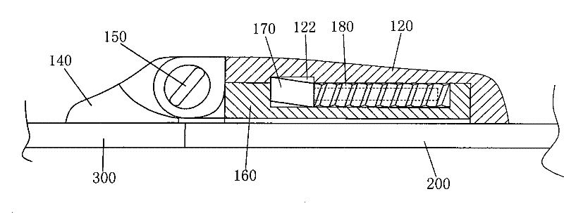
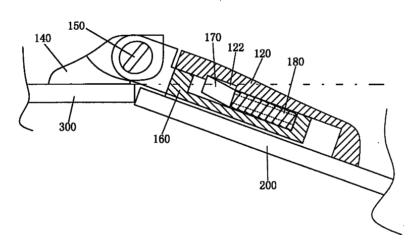
[0046] see Figure 8 and Figure 9 , the cross-section of the positioning guide member 170 is a parallelogram, and its three-dimensional shape is a parallelogram. 163, and inserted into the cavity 121 of the box body 120, the lower part of the front end 176 of the positioning guide member 170 withstands the inner wall 168 of the front end of the space 163, and the upper part of the front end 176 of the positioning guide member 170 withstands the The inner wall 123 at the front end of the notch 122 . The positioning guide member 170 can be made of stainless steel, cupronickel or manganese-phosphorus material.

Embodiment 2

[0048] see Figure 10 and Figure 11 , and the positioning guide member embodiment 1 is different in that the center of the tail 172 of the positioning guide member 170 is fixed with a guide shaft 171, and the outer diameter of the guide shaft 171 is adapted to the inner diameter of the spring 180; The length of the shaft 171 should meet the following requirements: when the spectacle arm 200 on the spectacle frame is in a natural state, the guide shaft 171 at the tail of the positioning guide member 170 that cooperates with the inner diameter of the spring 180 and the first joint assembly There is a certain gap in the inner wall 169 of the rear end of the space 163 of the main body 160; when the temples 200 on the spectacle frame are subjected to an external force, the temples 200 are opened outwards to a certain angle, and the spring 180 is not fully compressed to the end. The guide shaft 171 at the tail of the positioning guide member 170 first contacts the rear end inner w...

Embodiment 3

[0050] see Figure 12 , Figure 13 , Figure 5 and Figure 18 , in order to distinguish it from Embodiments 1 and 2 of the positioning guide member, the positioning guide member is represented by a reference numeral 190, the positioning guide member 190 is made of a material with good elasticity, and its front end is opened in a fork shape, so that the positioning The front end of the guide member 190 is bifurcated into upper and lower pages 194, 195, wherein the angle θ between the upper page 195 of the bifurcation and the vertical inner end surface 193 of the tail of the positioning guide member 190 is an obtuse angle, and the lower page of the bifurcation is an obtuse angle. The included angle θ1 between 194 and the vertical inner end surface 193 of the tail of the positioning guide member 190 is a right angle; After the box body 120 is inside the cavity 121, the tail end 192 of the positioning guide member 190 withstands one end of the spring 180, and the front end of t...


PUM


Abstract

The invention provides an eyeglass frame with a spring hinge mechanism. The spring hinge mechanism comprises a second joint component mainbody which is fixed on a peg head, a box body which is fixed on an eyeglass leg, a first joint component mainbody, a spring and a positioning and guiding component; the first joint component mainbody comprises a joint head, a hollow position which can receive the spring and the positioning and guiding component, a buffer which is arranged at the rear end of the hollow position, and a platform which is connected with the joint head and arranged at the front end of the hollow position; the box body is internally provided with a chamber which can receive the first joint component; the first joint component mainbody is connected with the second joint component mainbody; the box body is internally provided with a gap; when the positioning and guiding component and the spring are arranged on the hollow position of the first joint component mainbody and inserted into the chamber of the box body, the tail part of the positioning and guiding component pushes against one end of the spring, the lower part of the front end of the positioning and guiding component pushes against the internal wall of the front end of the hollow position and the upper part of the front end thereof pushes against the internal wall of the rear end of the gap; and the other end of the spring pushes against the internal wall of the rear end of the hollow position. The eyeglass frame has the advantages of compact structure, small volume, light weight, simple processing, lowcost, easy assembly and the like.

Description

【Technical field】 [0001] The invention relates to a spectacle frame which is a non-optical part of the spectacle, in particular to a spectacle frame with a spring hinge mechanism. 【Background technique】 [0002] With the improvement of living standards, people have higher and higher requirements for wearing glasses, and they are particular about the weight, size and comfort of wearing glasses. The face width of each user is different, which often causes the glasses legs to press the face and cause discomfort to the user. People have designed a kind of spectacle frame that spectacle leg can bend outwards for this reason, and spectacle leg on this spectacle frame is made of a kind of material with good elasticity; Or, spectacle leg is a kind of rigid material and makes, and in There is a spring hinge mechanism between the pile head connecting the spectacle frame and the rigid spectacle leg. The spring hinge mechanism can be easily expanded outwards with the help of external f...

Claims


Application Information

Patent Timeline
Patent Type & Authority Patents(China)
IPC IPC(8): G02C5/22G02C5/10G02C5/00
Inventor 朱裕前
Owner 朱裕前
Why Eureka
Try Eureka