Supercharge Your Innovation With Domain-Expert AI Agents!

car body

An automotive body, flange technology, applied in vehicle components, vehicle safety arrangements, superstructure sub-assemblies, etc., which can solve problems such as difficulty in complying with HIC limit values, increased beam resistance, etc.

Inactive Publication Date: 2016-12-21
GM GLOBAL TECH OPERATIONS LLC
View PDF6 Cites 0 Cited by
  • Summary
  • Abstract
  • Description
  • Claims
  • Application Information

AI Technical Summary

Problems solved by technology

However, the resistance of the beam increases when the deformation also affects the lower support part, or when the deformation reaches the rear end section of the upper support part, which is parallel to the direction of impact and therefore has a high resistance to deformation. up
This makes it difficult to comply with the permissible HIC (Head Injury Index) limit values ​​in the event of impact on the aforementioned beam

Method used


Image

  • car body
  • car body
  • car body

Examples


Embodiment Construction

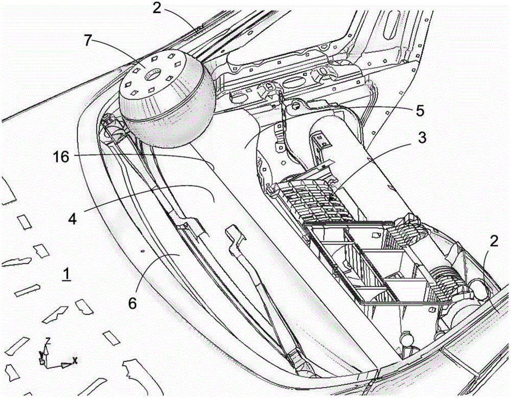
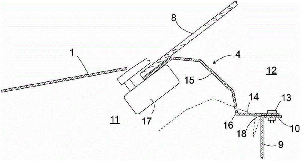
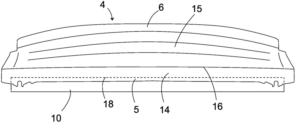
[0017] figure 1 A partial perspective view of an automobile body in which the invention may be used is shown. The rear area of ​​the front panel 1 and the adjoining windshield opening flanked by the A-pillar 2 on which the windshield is mounted in the completed motor vehicle can be seen. Dashboard trim in figure 1 has been removed and not shown in order to be able to show the components 3 of the instrument panel arranged therebeneath and the cross member 4 formed from the single-layer blank, which are covered under the trim of the instrument panel in the completed vehicle. The rear flange 5 of the cross member 4 rests on the upper edge of a bulkhead, not visible in the figure, extending between the passenger compartment and the engine compartment. The front flange 6 of the oblique beam supports the front lower edge of the windshield.

[0018] The impactor 7 shown on the windshield cross member 4 represents a position, when the car collided with an adult (pedestrian of norma...


PUM


Abstract

The invention relates to an automobile body, which has a front cover (1), a front windshield (8) rising upward from the rear edge of the front cover (1), and a front windshield (8) in the width direction of the front windshield (8). Extended beam (4), the front flange (6) of the beam supports the front lower edge of the front windshield (8), and the rear flange (5) is supported on the structural component (9) of the vehicle body and the first middle section (15) of the crossbeam extends from the rear upper edge of the front flange (6) to the rear flange (5), which extends beyond the The support surface (10) of the structural component (9) extends forward through a second intermediate section (14), and the intermediate sections (14, 15) pass through a flexure area (16) protruding towards the engine compartment (11). )connected together.

Description

technical field [0001] The invention relates to an automobile body, which has a front cover, a front windshield rising upward from the rear edge of the front cover, and a beam supporting the front lower edge of the front windshield. Background technique [0002] A motor vehicle is known from DE 10 2007 012 830 A1 in which the cross member supporting the windshield is assembled from two supporting parts connected to each other at their front and rear edges. The upper support part is curved upwards in cross-section and has a front section that supports the front edge of the windshield rising against the direction of travel, a substantially horizontal middle section and a rear section that slopes steeply downwards against the direction of travel. When the vehicle hits a passer-by while driving, the passer-by then usually falls obliquely upwards onto the hood, wherein he turns about an axis approximately on the front flange of the hood. For an adult of normal height, the head w...

Claims


Application Information

Patent Timeline
Patent Type & Authority Patents(China)
IPC IPC(8): B62D25/08
CPCB60R21/34B60R2021/343
Inventor S.沃尔夫J.谢弗
Owner GM GLOBAL TECH OPERATIONS LLC
Features
  • R&D
  • Intellectual Property
  • Life Sciences
  • Materials
  • Tech Scout
  • Unparalleled Data Quality
  • Higher Quality Content
  • 60% Fewer Hallucinations
Learn More