Liquid ejecting head, liquid ejecting apparatus and actuator apparatus

a technology of actuator apparatus and liquid ejector, which is applied in the direction of piezoelectric/electrostrictive/magnetostrictive devices, piezoelectric/electrostriction/magnetostriction machines, piezoelectric/electrostriction/magnetostriction machines, etc., to achieve the effect of suppressing the reduction of displacement amoun

Inactive Publication Date: 2014-09-18
SEIKO EPSON CORP
View PDF1 Cites 12 Cited by
  • Summary
  • Abstract
  • Description
  • Claims
  • Application Information

AI Technical Summary

Benefits of technology

[0007]An advantage of some aspects of the invention is to provide a liquid ejecting head, a liquid ejecting apparatus and an actuator apparatus that have high reliability by suppressing the influence of increase of a residual distortion of piezoelectric elements included therein and thereby suppressing reduction of a displacement amount thereof over a long period of time.
[0009]According to this first aspect, the first piezoelectric elements and the second piezoelectric element compensate for each other's increase of a residual distortion, and thus, the influence of the increase of a residual distortion due to repeated driving operations is suppressed, and it becomes possible to suppress reduction of a displacement amount thereof.
[0010]Here, in the first aspect, preferably, the at least one direction corresponds to a direction in which the nozzle openings are aligned. According to this configuration, it becomes possible to effectively deform the vibration plate by using the two first piezoelectric elements and the second piezoelectric element.
[0013]According to this second aspect, the variation of the characteristic of liquid ejection is suppressed over a long period of time, and it becomes possible to realize a liquid ejecting apparatus with enhanced reliability.
[0014]In the second aspect, preferably, the liquid ejecting apparatus further includes a control apparatus that supplies the first piezoelectric elements with a first driving signal and the second piezoelectric element with a second driving signal different from the first driving signal. According to this configuration, the first piezoelectric elements and the second piezoelectric element are driven at mutually different time points, and it becomes possible to allow the first piezoelectric elements and the second piezoelectric element to perform driving operations most suitable for liquid ejection.
[0016]According to this third aspect, the first piezoelectric elements and the second piezoelectric element compensate for each other's increase of a residual distortion, and thus, the influence of the increase of a residual distortion due to repeated driving operations is suppressed, and it becomes possible to suppress reduction of a displacement amount thereof.

Problems solved by technology

Nevertheless, there is a problem that, in a piezoelectric element having been subjected to repeated driving operations, a crystal structure of a piezoelectric substance layer thereof has been changed and an amount of displacement of the piezoelectric element becomes smaller than an amount of displacement thereof at the beginning of the repeated driving operations.
Further, such a problem similarly exists in a liquid ejecting head which ejects liquid other than the ink.
Moreover, this problem is not a problem limited to an actuator apparatus mounted in the liquid ejecting head but a problem which similarly exists in an actuator apparatus for use in a different kind of device.

Method used


Image

  • Liquid ejecting head, liquid ejecting apparatus and actuator apparatus
  • Liquid ejecting head, liquid ejecting apparatus and actuator apparatus
  • Liquid ejecting head, liquid ejecting apparatus and actuator apparatus

Examples


embodiment 1

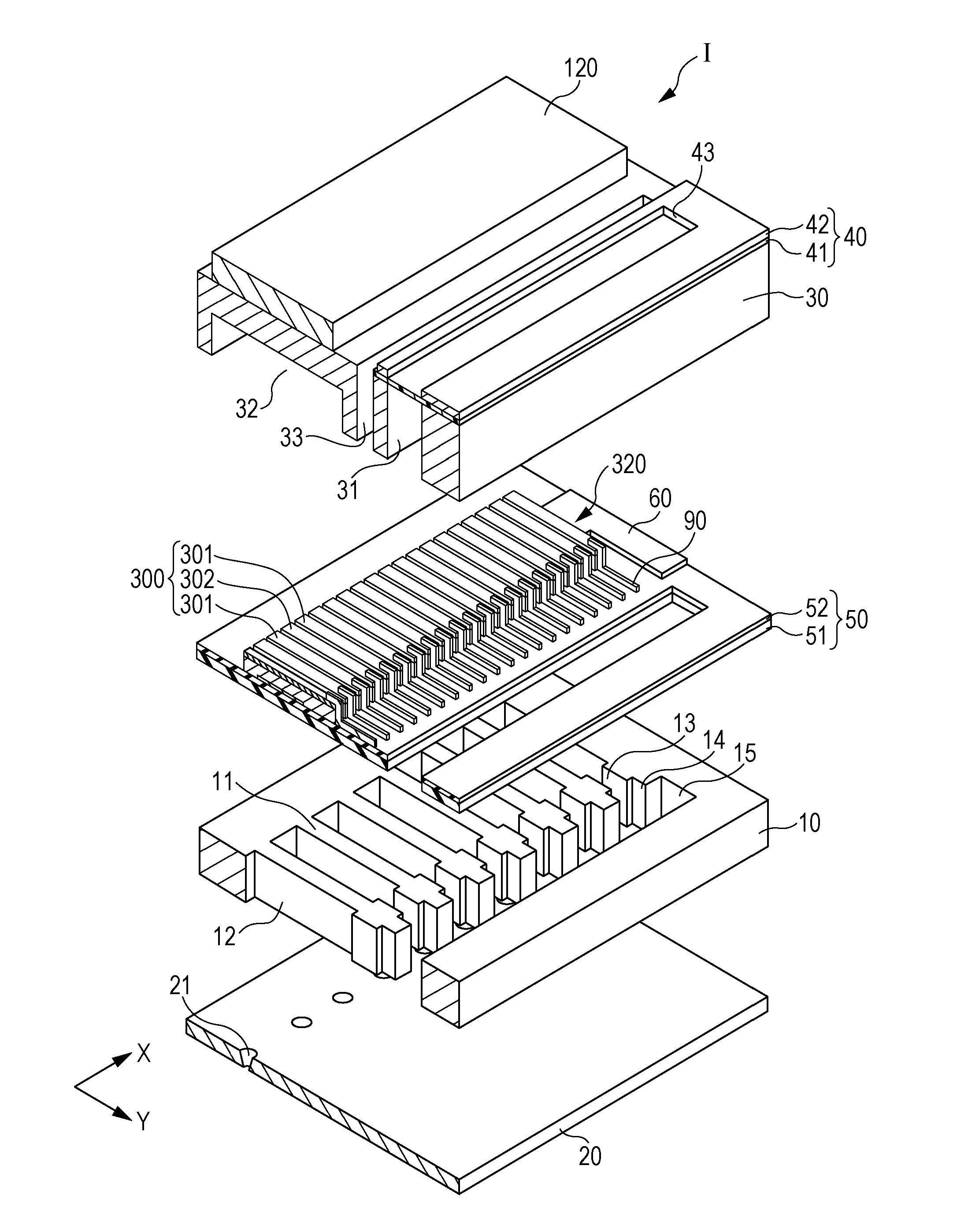
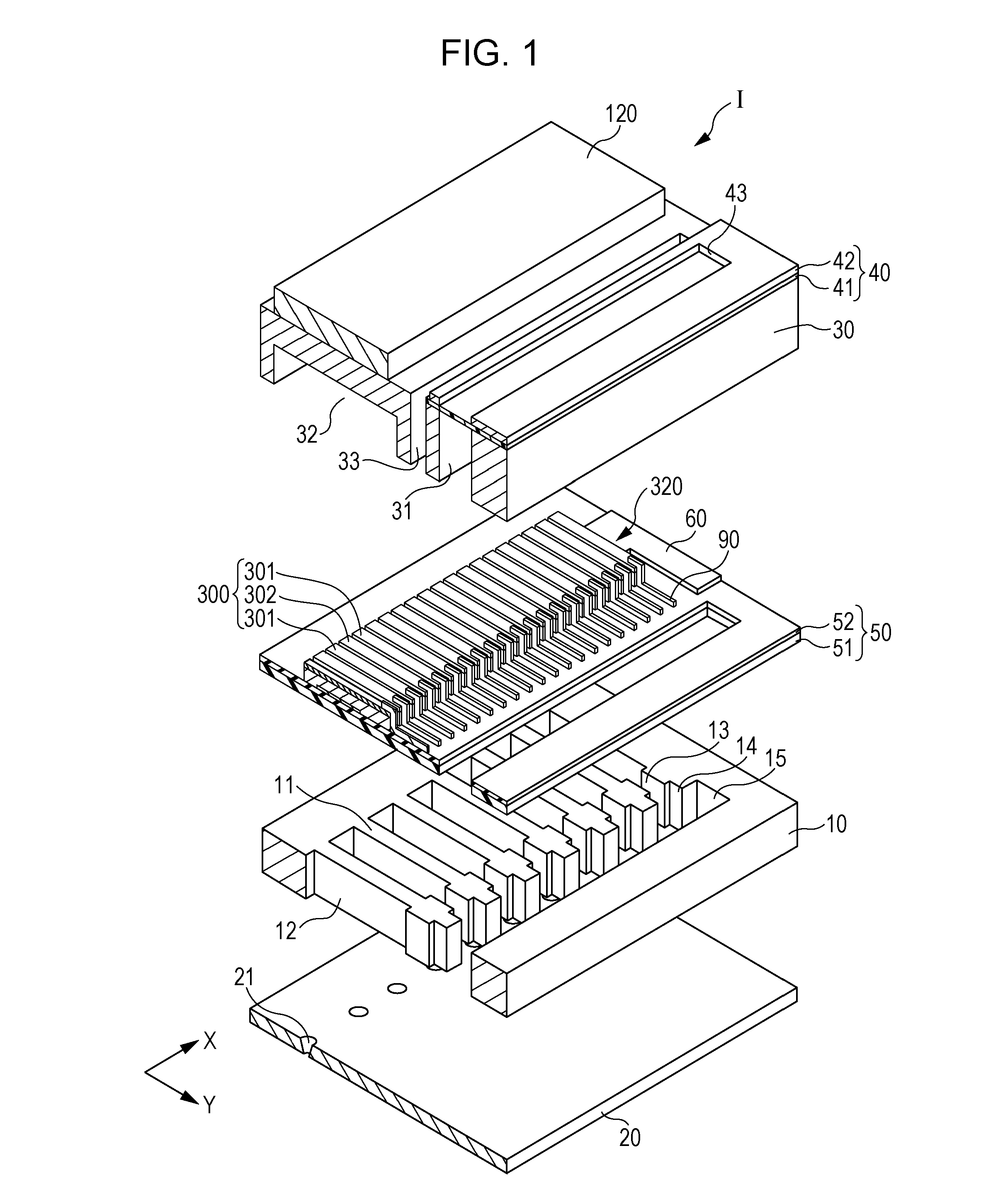
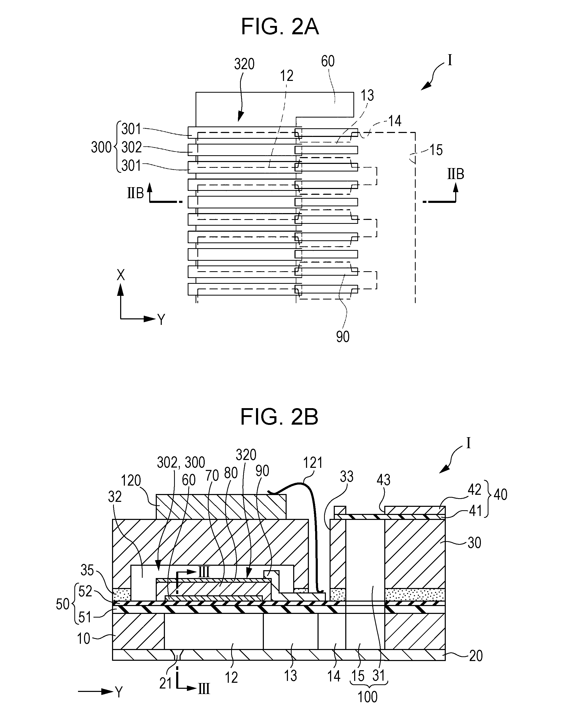
[0029]FIG. 1 is a disassembled perspective view of an ink jet recording head which is an example of a liquid ejecting head according to this embodiment 1 of the invention; FIG. 2A is a plan view of a piezoelectric element side of a flow path formation substrate; FIG. 2B is a cross-sectional view taken along the line IIB-IIB of FIG. 2A; and FIG. 3 is a cross-sectional view taken along the line III-III of FIG. 2B.

[0030]As shown in FIGS. 1, 2A, 2B and 3, a flow path formation substrate 10 included in an ink jet recording head I, which is an example of a liquid ejecting head according to this embodiment, is formed of, for example, a silicon single-crystal substrate. In this flow path formation substrate 10, pressure generation chambers 12 partitioned by a plurality of partitioning walls 11 are arranged in parallel along a direction in which a plurality of nozzle openings 21, through each of which ink of the same color is ejected, align. Hereinafter, this direction will be referred to as...


PUM


Abstract

A liquid ejecting head includes a flow path formation substrate provided with a pressure generation chamber communicated with at least one nozzle opening through which liquid is ejected; and an actuator apparatus including a vibration plate provided at one face side of the flow path formation substrate and a plurality of piezoelectric elements being formed on the vibration plate. The actuator apparatus includes two first piezoelectric elements arranged at positions facing edge portions in at least one direction of the pressure generation chamber and a second piezoelectric element arranged between the two first piezoelectric elements.

Description

BACKGROUND[0001]1. Technical Field[0002]The present invention relates to a liquid ejecting head, a liquid ejecting apparatus and an actuator apparatus each ejecting liquid through nozzle openings thereof, and in particular, relates to an ink jet recording head and an ink jet recording apparatus each ejecting ink as the liquid.[0003]2. Related Art[0004]In various types of piezoelectric elements, there exists a type of piezoelectric element which is for use in a liquid ejecting head or the like and which is configured such that a piezoelectric substance layer made of a piezoelectric material having an electromechanical conversion function, such as a crystallized dielectric material, is interposed between two electrodes. In addition, as a typical example of the liquid ejecting head, there exists, for example, an ink jet recording head which is configured such that, part of a pressure generation chamber communicated with a nozzle opening through which ink droplets are ejected is formed ...

Claims


Application Information

Patent Timeline
Patent Type & Authority Applications(United States)
IPC IPC(8): B41J2/14H01L41/09B41J2/07
CPCB41J2/14201H01L41/09B41J2/07B41J2/14233B41J2002/14338B41J2202/11B41J29/38B41J2002/14362B41J2002/14241B41J2002/14491B41J2/04581B41J2/04588B41J2002/14419H10N30/802H10N30/2047
Inventor YOKOYAMA, NAOTO
Owner SEIKO EPSON CORP
Why Eureka
Try Eureka