Lithium-base battery

A battery, lithium-based technology, used in dry batteries, secondary batteries, battery pack components, etc., can solve the problems of diaphragm 3 rupture, burst, battery ignition, etc., and achieve the effect of protecting the corners

Inactive Publication Date: 2002-04-03
ITOCHU CO LTD
View PDF1 Cites 11 Cited by
  • Summary
  • Abstract
  • Description
  • Claims
  • Application Information

AI Technical Summary

Problems solved by technology

In this case, since the current only flows in the battery, it is useless to limit the current with the PTC device in method (2), and the shut-off diaphragm in method (3) cannot prevent the metal rod 9 from piercing through the diaphragm 3 At the moment of electrodes 1 and 2, a large current flows between positive electrode 1 and negative electrode 2
[0006] When the battery is broken, the separator 3 usually ruptures, causing a short circuit between the positive electrode 1 and the negative electrode 2
In this case, the PTC device in method (2) is useless, and the shut-off diaphragm in method (3) cannot prevent the moment when the metal rod 9 pierces the electrodes 1 and 2 through the diaphragm 3, a large current flows in the positive electrode 1 and flow between the negative electrode 2
[0007] In this way, the disadvantage of the prior art battery is that if a serious accident occurs due to external causes, for example, if a nail pierces the battery or the battery is broken, a very large short-circuit current flows momentarily between the electrodes, which makes the battery Exposed to high temperature / high pressure, as a result there is a risk of the battery igniting and / or bursting
Therefore, there is a problem that the prior art batteries cannot maintain sufficient safety

Method used


Image

  • Lithium-base battery
  • Lithium-base battery
  • Lithium-base battery

Examples


no. 1 approach

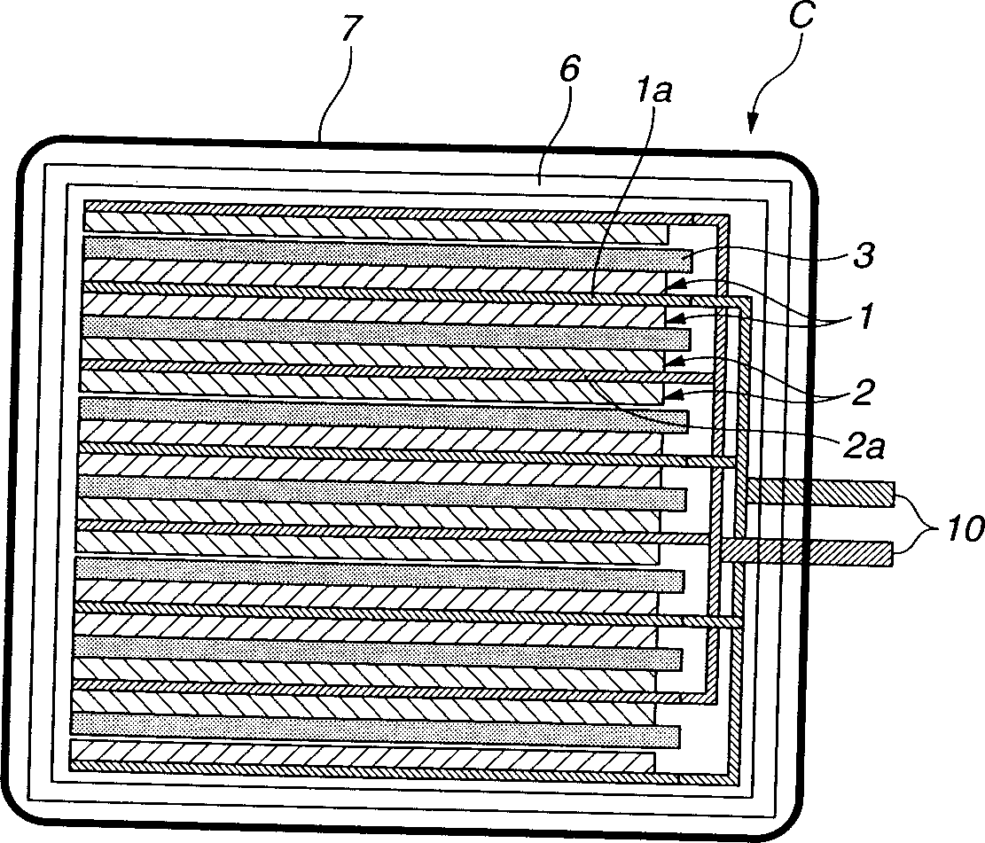
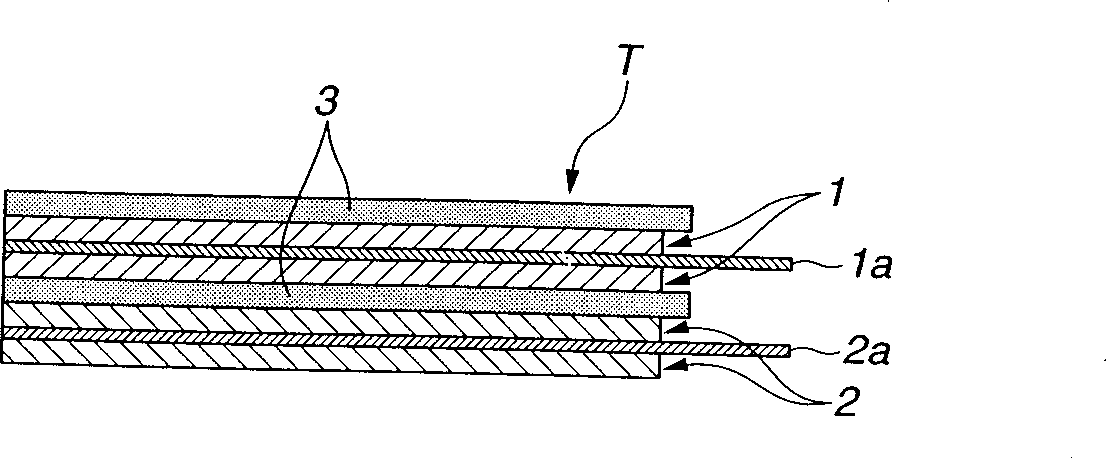
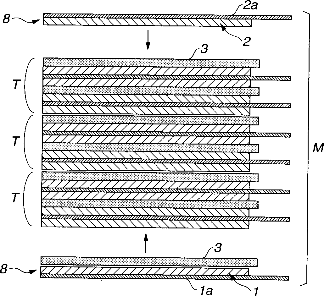
[0037] figure 1 is a schematic cross-sectional view of a lithium-based battery C according to a first embodiment of the present invention; figure 2 is a schematic cross-sectional view of the unit cell T; and image 3 is a schematic cross-sectional view illustrating the assembly of the battery structure group M of the lithium-based battery.

[0038] see figure 1 , the lithium-based battery C according to the first embodiment is obtained by stacking unit cells T one by one to form a battery structure group M, wherein each unit cell contains a positive electrode 1, a negative electrode 2, and a separator disposed therebetween 3; installing the battery structure group M in the battery container 6; filling the battery container 6 with electrolyte; and covering the battery container with an ion-impermeable and extensible polymer sheet 7 with a tensile elongation of 1% or more 6 on the peripheral surface. Such as figure 1 As shown, a positive current collector 1a is connecte...

no. 2 approach

[0129] Figure 4 is a schematic cross-sectional view of a battery structure group M of a lithium-based battery according to a second embodiment of the present invention. The lithium-based battery of this embodiment includes: a battery structure group made by stacking unit cells T, each unit cell T including a positive electrode 1, a negative electrode 2, and a separator 3 interposed therebetween, and an electrolyte, wherein the battery structure group The periphery of M is covered with an ion-impermeable and extensible high polymer sheet 7 having a tensile elongation of 1% or more.

[0130] In this case, after the outer periphery of the battery structure group M is covered with the stretchable polymer sheet, the electrolyte can be injected or poured into the battery. Alternatively, the electrolyte can be pre-infused into the battery structure, and then the outer periphery of the battery structure is covered with an extensible polymer sheet.

[0131] In the second embodiment,...

no. 3 approach

[0137] Figure 8 and 9 is a sectional view of a lithium-based battery according to a third embodiment of the present invention. The structure of this lithium-based battery is such that a battery structure group made by stacking three unit cells T including a positive electrode 1, a negative electrode 2 and a diaphragm 3 interposed therebetween.

[0138] In this case, if Figure 10 As shown, a positive electrode 1 and a negative electrode 2 of a unit cell T are respectively formed on one surface of a positive electrode current collector 1a and a negative electrode current collector 2a, and are arranged to face each other with a separator therebetween. In other words, the positive electrodes 1 of the unit cells T are arranged back to back, and the similar negative electrodes 2 are also arranged back to back. And, if Figure 8 As shown, by stacking unit cells T 1 , T 2 and T 3 The outer peripheral surface of the formed battery structure group is covered with an ion-imperm...


PUM

PropertyMeasurementUnit
electrical conductivityaaaaaaaaaa
elongationaaaaaaaaaa

Abstract

A lithium based battery includes a cell structure group formed by stacking unit cells each including a positive electrode, a negative electrode, and a separator interposed therebetween, or formed by repeatedly folding or winding an integral body of the unit cells; a battery container for containing the cell structure group; and an electrolyte, which is poured in the battery container after the cell structure group is contained in the battery container. The outer peripheral surface of the battery container is covered with an ion impermeable and extensible high polymer sheet having a tensile elongation percentage of 1% or more. With this configuration, even if there happens such a severe accident that nail pieces the battery or the battery is crashed, it is possible to prevent a large short-circuit current from flowing between the positive and negative electrodes, and hence to ensure a higher safety of the battery.

Description

technical field [0001] The present invention relates to a lithium-based battery, such as a lithium secondary battery or a lithium-ion secondary battery, which can be operated with high safety. Background technique [0002] The nonaqueous secondary battery is assembled by preparing a battery structural group formed by stacking unit cells each including a positive electrode, a negative electrode, and a separator disposed therebetween, or the battery structural group is prepared by winding the whole of a unit battery; installing the battery structure group in a battery container; and filling the battery container with a non-aqueous electrolyte. In addition, the positive electrode is made by supporting a positive electrode active material such as lithium cobaltate on a current collector such as aluminum foil, and the negative electrode is made by supporting a negative electrode active material such as graphite on a current collector such as copper foil. made. [0003] The abov...

Claims


Application Information

Patent Timeline
Patent Type & Authority Applications(China)
IPC IPC(8): H01M6/10H01M6/42H01M6/50H01M10/04H01M10/05H01M10/0525H01M10/36H01M10/42H01M50/121H01M50/133
CPCY02E60/12H01M10/0413H01M10/0525H01M10/4235H01M10/05H01M2002/0297H01M6/50Y02T10/7011H01M6/42H01M2/0277H01M2/0275H01M6/10H01M2/0267H01M2/0287Y02E60/10H01M50/124H01M50/131Y02P70/50H01M50/133H01M50/121H01M10/058
Inventor 佐藤贵哉吉田浩桥本善三
Owner ITOCHU CO LTD
Why Eureka
Try Eureka