Eureka AIR delivers breakthrough ideas for toughest innovation challenges, trusted by R&D personnel around the world.

Cast support seat

A technology of support and hinged seat, which is applied in the direction of earth mover/excavator, construction, etc., can solve the problems of high manufacturing cost and easy failure, and achieve the effect of ensuring quality, strengthening strength, and preventing support damage and failure

Inactive Publication Date: 2013-06-05
GUANGXI LIUGONG MASCH CO LTD
View PDF6 Cites 4 Cited by
  • Summary
  • Abstract
  • Description
  • Claims
  • Application Information

AI Technical Summary

Problems solved by technology

[0003] The purpose of the present invention is to provide a casting support with low manufacturing cost and high reliability, aiming at the disadvantages of high manufacturing cost and easy failure caused by the strengthening method of the middle partition of the existing casting support

Method used


Image

  • Cast support seat
  • Cast support seat
  • Cast support seat

Examples


Embodiment 1

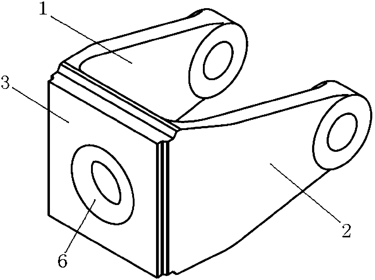
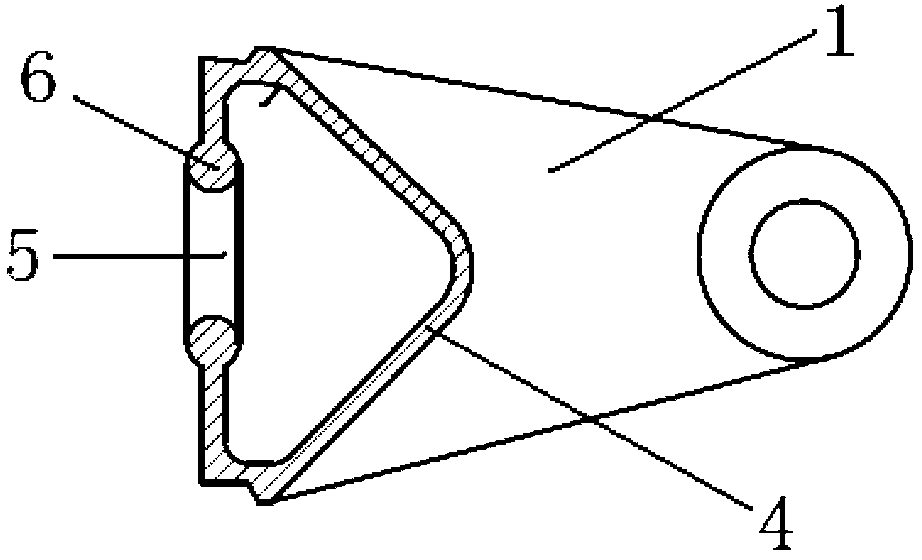
[0019] like figure 1 figure 2 As shown, the casting support in this embodiment is formed by casting at one time, which includes a left hinged seat 1 and a right hinged seat 2, and the bottoms of the left hinged seat 1 and the right hinged seat 2 are connected by a square middle partition 3, There is a V-shaped reinforcing plate 4 between the left hinged seat 1 and the right hinged seat 2, the two ends of the V-shaped reinforced plate are respectively connected with the left hinged seat 1 and the right hinged seat 2, and the two sides are connected with the middle partition, V-shaped Reinforcement plate 4, left hinged seat 1, right hinged seat 2, and middle partition 3 form a box-shaped structure, on which middle partition 3 is provided with a sand cleaning port 5, and on the edge of the sand cleaning port 5 there is a surrounding sand cleaning port. The closed annular rib 6 of the mouth, the cross section of the annular rib 6 is roughly circular, its diameter is greater than...

Embodiment 2

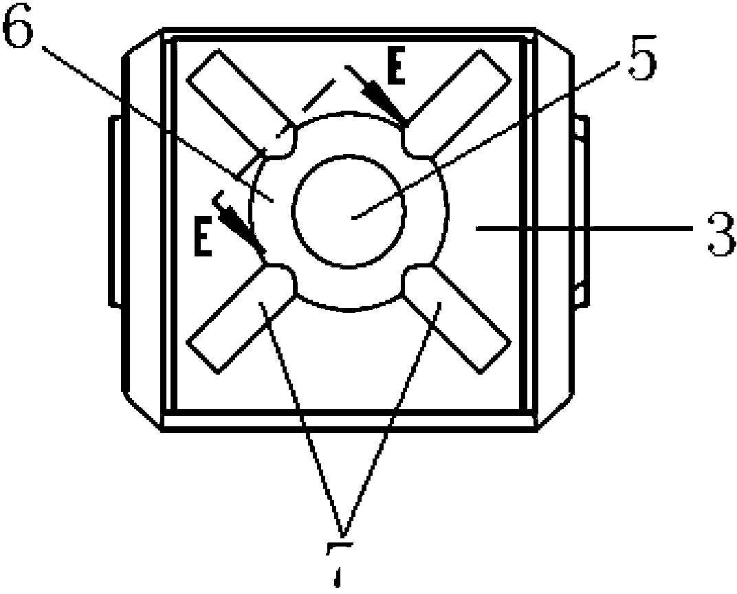
[0022] Compared with Embodiment 1, this embodiment differs in that an anti-torsion rib 7 is also provided on the outside of the middle partition, such as image 3 As shown, the number of torsion ribs 7 is four, one end of which points to the center end of the middle part of the middle partition 3, the center end is connected with the annular rib 6, and the other end of the torsion rib 7 points to the middle partition 3 A corner of , which is consistent with the diagonal direction of the middle partition 3; as Figure 4 As shown, the cross section of the torsion rib 7 is semicircular, and the cross section of the torsion rib 3 can also be semi-elliptic, etc.; . In this embodiment, the anti-torsion ribs 7 can be arranged on the outside of the middle partition 3, or on the inside of the middle partition 3, or both inside and outside of the middle partition 3, and the anti-torsion ribs 7 on the inside and outside sides The twisted ribs are symmetrical about both sides of the mid...


PUM


Abstract

The invention relates to a cast support seat. The cast support seat aims at overcoming the shortages that a median septum strengthening method adopted by an existing cast support seat is high in manufacture cost and effectiveness is easy to lose. The cast support seat is formed integrally through casting and comprises a left hinging seat, a right hinging seat and a rectangular median septum arranged at the bottom of the support seat and used for connecting the left hinging seat and the right hinging seat. A sand cleaning opening is formed in the median septum. A closed annular rib enclosing the sand cleaning opening is arranged on the edge of the sand cleaning opening. According to the cast support seat, the enclosed annular rib is arranged on the sand cleaning opening so that intensity of the sand cleaning opening is enhanced, stress in the sand cleaning opening is reduced, stress concentration is avoided and the support seat is prevented from being damaged and losing effectiveness caused by cracking in the sand cleaning opening portion due to torsion of the support seat. Meanwhile, a strengthening structure is formed when the support seat is formed so that following processing process of a traditional cast support seat is avoided and quality is easy to guarantee.

Description

technical field [0001] The invention relates to a support, in particular to a cast support formed by casting. Background technique [0002] The front and rear ends of the boom in the excavator are provided with substantially U-shaped hinged supports for hinged connection with the stick and the vehicle frame. Because the excavator has lateral loads on the bearings when digging, which generates a large torque on the bearings, most of the existing bearings are integrally cast. In order to further strengthen the strength of the support, there is a V-shaped reinforcement plate connecting the left and right hinged seats at the bottom of the support. The V-shaped reinforcement plate is formed together when the support is cast. The partition forms a box-shaped structure, and due to the needs of the manufacturing process, the sand-cleaning port of the box-shaped structure during casting is usually set on the middle partition. Because the support often bears a huge side load, a torq...

Claims


Application Information

Patent Timeline
Patent Type & Authority Applications(China)
IPC IPC(8): E02F9/00
Inventor 冯豪唐建国向上升蒋绍军施朝坤
Owner GUANGXI LIUGONG MASCH CO LTD
Why Eureka
Eureka Blog
Learn More