Electronic locks

A technology of electronic locks and lock cylinders, applied in the field of electronic locks, can solve the problems of high cost and complex structure of electronic locks, and achieve the effects of ensuring life and property safety, improving anti-theft functions, and reducing power consumption

Inactive Publication Date: 2016-08-24
罗奇
View PDF6 Cites 0 Cited by
  • Summary
  • Abstract
  • Description
  • Claims
  • Application Information

AI Technical Summary

Problems solved by technology

[0004] The purpose of the present invention is to provide an electronic lock to solve the problems of complex structure and high cost in the prior art

Method used


Image

  • Electronic locks
  • Electronic locks
  • Electronic locks

Examples


Embodiment 1

[0066] like figure 1 As shown, this embodiment discloses an electronic lock, which is mainly composed of five parts: a safety lock device, a power supply system, a lock tongue, a lock cylinder, and a heaven and earth rod mechanism, wherein:

[0067] The safety lock device is electrically connected with the drive motor 2, and it can be a combination lock device. After the user enters the correct password, the safety lock device is opened and connected to the power supply system and the drive motor 2. The drive motor 2 is powered and enters the working state; It is a fingerprint lock device or other mature lock devices in the prior art, so it will not be described in detail in this embodiment.

[0068] Power supply system, preferably powered by batteries, such as Figure 18 As shown, the battery slot for installing the battery is designed on the outside of the electronic lock (i.e. outside the door), which greatly facilitates the user to replace the battery and does not have to...

Embodiment 2

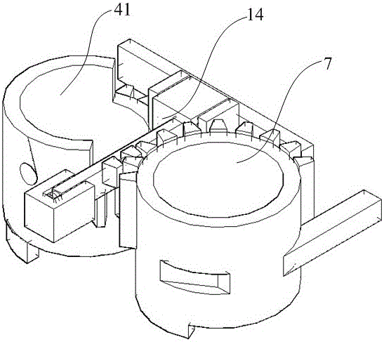
[0086] like Figure 20 , 21 As shown, the difference between this embodiment and Embodiment 1 is that, in order to better realize the present invention, facilitate users to use, and increase its function of opening the door through a key, the second lock core 7 includes a cylindrical lock core 71 located in a circular The upper end surface of the cylindrical lock core 71, the key lock core connection hole 75 for connecting the mechanical lock core providing a jack for the key, and the stop rod 72 located at the lower end of the cylindrical lock core 71 and engaged with it; wherein, The outside of the cylindrical lock cylinder 71 is provided with an engaging tooth 74 and a second rotating block 73 that match the teeth 415 on the outer wall of the third lock cylinder 41, and the end of the stop rod 72 is located in the groove of the "U"-shaped linkage 63. Inside, the position corresponding to the second lock core 7 on the lock body 1 is provided with a connecting sleeve 76 fixe...


PUM


Abstract

The invention discloses an electronic lock, and belongs to the field of safety technology protection. The electronic lock solves the problems that in the prior art, the electronic lock is complex in structure, high in cost, inconvenient to use. The electronic lock comprises a lock body provided with a cavity, a lock cover, a drive motor, a power supply system, a coded lock device, a first lock tongue, combined type lock core, a first lock core, a second lock tongue, a second lock core and a heaven and earth rod mechanism. The power supply system supplies power for the drive motor, and the coded lock device is electrically connected with the power supply system. The first lock tongue is arranged on the upper end of the lock body and can penetrate through the side face of the lock body, and the combined type lock core can rotate around the lock body and is used for dragging the first lock tongue back into the lock body. The first lock core is used for pushing the combined type lock core and is meshed with an output shaft of the drive motor. The second lock tongue is arranged on the lower end of the lock body and can penetrate through the side face of the lock body, and the second lock core is meshed with the combined type lock core and driven by the combined type lock core and is used for dragging the second lock tongue back into the lock body. The second lock core is fixedly arranged on one side, opposite to the first lock tongue and the second lock tongue, of the lock body, and achieves contracting through the combined type lock core and the second lock core. The heaven and earth rod mechanism achieves popping-up through a first springing control mechanism and a second springing control mechanism.

Description

technical field [0001] The invention relates to an electronic lock, in particular to an electronic lock. Background technique [0002] Electronic locks are mainly used in the field of security technology prevention, especially electronic locks used with anti-theft doors, because of their excellent anti-theft effect, they are welcomed by the masses. At present, electronic locks can be roughly divided into: button-type electronic locks, electronic key-type electronic locks, touch-type electronic locks, etc. The above-mentioned electronic locks have good anti-theft effects in terms of anti-theft function, but the main improvement of this type of electronic lock lies in the control The structure of the unlocking method is very complicated, but the mechanical structure of the lock has not changed much, so that the cost of electronic locks is relatively expensive. For example, the minimum price of imported electronic locks is more than 1,000 yuan. It also needs more than 400 yuan...

Claims


Application Information

Patent Timeline
Patent Type & Authority Patents(China)
IPC IPC(8): E05B63/14E05B47/00E05B17/22E05B15/00E05B15/10
Inventor 不公告发明人
Owner 罗奇
Why Eureka
Try Eureka