Door locking device

A technology of door lock and unlock state, applied in the direction of doors, building locks, vehicle locks, etc., can solve the problems of troublesome assembly and poor assembly, and achieve the effect of improving assembly.

Active Publication Date: 2013-06-05
U SHIN LTD
View PDF8 Cites 6 Cited by
  • Summary
  • Abstract
  • Description
  • Claims
  • Application Information

AI Technical Summary

Problems solved by technology

[0005] In this door lock device, when the rotation lever 102 is inserted into the support shaft 103, the other end 104a of the spring 104 needs to be held against the biasing force at the position where the rotation lever 102 is to be inserted into the support shaft 103, and thus there is a problem that assembly is troublesome.
[0006] In addition, when the inner cable connecting portion 102a provided on the end portion of the turning lever 102 is exposed to the outside from the opening (not shown) of the second case member, it is necessary to overcome the acting force in the Figure 12 At the position indicated by the dashed-two dotted line in (B), the rotating rod 102 is held by a jig or by hand, so the assemblability is poor.

Method used


Image

  • Door locking device
  • Door locking device
  • Door locking device

Examples


Embodiment Construction

[0064] Hereinafter, embodiments of the present invention will be described with reference to the drawings.

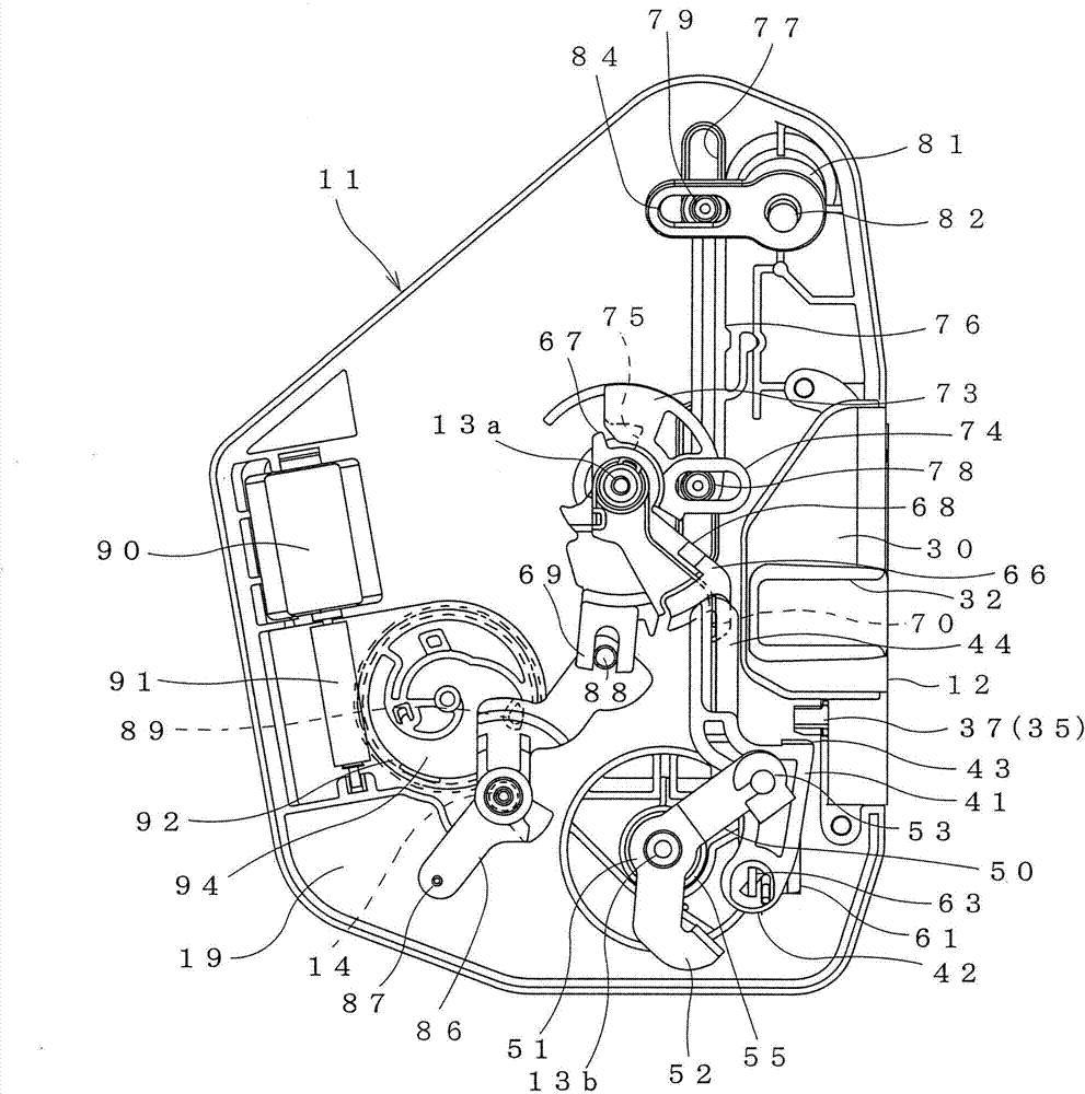
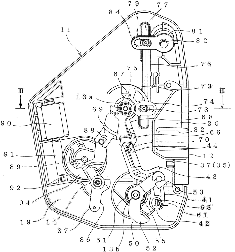
[0065] figure 1 and figure 2 It is door lock device which shows embodiment of this invention. The door lock device is assembled on the door of the vehicle, and can be arranged with the striker 1 (refer to Figure 6 (B)) Lock and disengage. The door lock device is provided with: a latch mechanism that engages with the striker 1; and a lock mechanism that switches the engagement state of the striker 1 by the latch mechanism to an unlocked state (can be released) and a locked state (cannot be released).

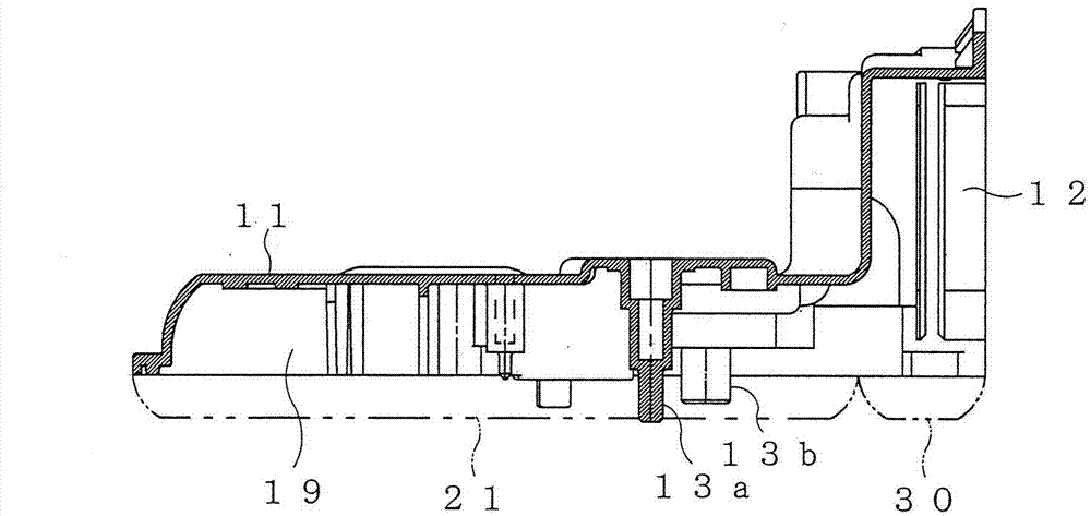
[0066] Such as image 3 As shown, the first case member 11 in which the components constituting the latch mechanism and the lock mechanism are arranged has an L-shape in plan view, and includes a latch mechanism arrangement portion 12 and a lock mechanism arrangement portion 19 .

[0067] The sub-housing 30 is assembled on the latch mechanism arrangement part 12 of...


PUM


Abstract

An object of the invention is to provide a door locking device capable of increasing assembly performance. The door locking device comprises a latch mechanism, a lock mechanism, housings (11, 12), a rotary rod (50) and an elastic component (55) for applying a force for rotating around a supporting shaft (13b) to the rotary rod (50). The door locking device is provided with a temporary fixing portion (17) for temporally fixing rod-side end portion (56) of elastic component (55) on an assigned position on a rotation track of the rotary rod (50). When the rotary rod (50) is in an assembling position assembled on a first housing component (11), the temporary fixing portion (17) enables the rod-side end portion (56) to be not engaged with the rotary rod (50); and when the rotary rod (50) rotates from the assembling position to a finished position that the door locking device is finished, the temporary fixing portion (17) enables the rod-side end portion (56) of the elastic component (55) to be kept at an engaging startup position where the rod-side end portion (56) of the elastic component (55) starts to engage with the rotary rod (50).

Description

technical field [0001] The present invention relates to a door lock device mounted on a vehicle door. Background technique [0002] The door of the vehicle is provided with a door lock device that is detachably engaged with a substantially U-shaped striker fixed to the vehicle body. The door lock device includes a latch mechanism for locking a striker and a lock mechanism for releasing the latch mechanism from locking the striker. [0003] Patent Document 1 describes a door lock device in which a latch mechanism, a lock mechanism, an electric actuator, and the like are accommodated and held in a single lock housing. Such a door lock device includes a pivot lever biased by an elastic member as one member constituting a lock mechanism. For example, if Figure 12 As shown in (A), the first housing member 101 includes: a support shaft 103 that supports the rotation lever 102 to be rotatable; a cylindrical spring mounting part 105 that is provided on the outer periphery of the ...

Claims


Application Information

Patent Timeline
IPC IPC(8): E05B65/32E05B85/24B60J5/00E05B79/08
Inventor 山形干雄赤木伸哉
Owner U SHIN LTD
Why Eureka
Try Eureka