Floating type brake pad for train

A brake pad, floating technology, applied in the direction of brake parts, brake types, brakes with movable brake parts, etc., can solve problems such as support failure, and achieve the effect of average stress and large amount of elasticity

Active Publication Date: 2013-06-05
BEIJING TIANYISHANGJIA NEW MATERIAL
View PDF8 Cites 14 Cited by
  • Summary
  • Abstract
  • Description
  • Claims
  • Application Information

AI Technical Summary

Problems solved by technology

[0005] For this reason, the technical problem to be solved by the present invention is that the pawls of the elastic support parts of the existing train brake pads do not stre

Method used


Image

  • Floating type brake pad for train
  • Floating type brake pad for train
  • Floating type brake pad for train

Examples


Embodiment 1

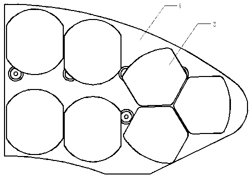
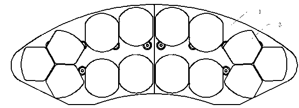
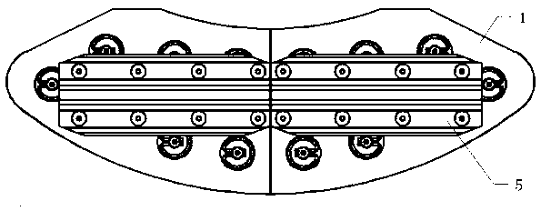
[0038] Such as Figure 1-9 Shown is the floating brake pad for trains of the present invention, which includes: a back plate 1 formed with a plurality of positioning holes 11, two of the back plates 1 are spliced ​​into a brake pad back plate; several friction blocks 3, It includes a friction part 31, a positioning part 32 inserted into the positioning hole 11, and a support part 33 arranged between the friction part 31 and the positioning part 32, the support part 33 is a spherical structure, and the support The spherical surface of the part 33 protrudes in the direction of the positioning part 32; several snap springs 4, the snap springs 4 are snapped on the positioning part 32, and the friction block 3 is connected to the positioning part 3 with a certain floating amount. on the backboard 1; also includes an elastic support piece 2 arranged between the friction block 3 and the backboard 1, and the elastic support piece 2 includes: a spherical support surface 21, which fits ...

Embodiment 2

[0049] The structure of this embodiment is basically the same as that of Embodiment 1, and the difference is that:

[0050] Such as Figure 10 As shown, in this embodiment, the spherical support surface 21 is composed of a section of spherical surface, and the spherical support surface 21 is in surface contact with the support portion 33 of the friction block 3, instead of the edge in the first embodiment. The spherical part c and the bottom spherical part d form the spherical supporting surface 21. In this embodiment, the arrangement of the spherical supporting surface 21 makes the processing of the elastic supporting sheet more convenient.


PUM

PropertyMeasurementUnit
Cone angleaaaaaaaaaa

Abstract

The invention relates to a floating type brake pad for a train. The floating type brake pad comprises a rear panel, a friction block, a clamping spring and an elastic supporting plate arranged between the friction block and the real panel. The elastic supporting plate comprises a ball supporting face and a supporting pawl arranged outside the ball supporting face. The ball supporting face is attached to a ball supporting portion of the friction block. A guiding hole suitable for a locating portion of the friction block to penetrate through is molded at the center of the bottom of the ball supporting face. The supporting pawl extends from the edge of the ball supporting face to the bottom of the ball supporting face and tends to a direction away from the guiding hole. A connecting edge of the supporting pawl and an edge of the ball supporting face are connected through a smooth transition section, and the supporting pawl and a supporting edge extend to exceed the bottom of the ball supporting face. The floating type brake pad for the train solves the problem that a pawl of an elastic supporting piece portion of the brake pad does not stretch outwards and is bent inwards, the elastic supporting plate can be stretched outwards along the direction of the supporting pawl during stress, and supporting failure of a corresponding portion is avoided.

Description

technical field [0001] The invention relates to a floating brake pad for a train, which belongs to the technical field of train braking. Background technique [0002] At present, in high-speed train brakes, disc brake structures are usually used. The disc brake structure mainly includes a brake disc and a brake pad. The above-mentioned brake structure consumes the kinetic energy of the moving vehicle or equipment through the mutual friction between the brake disc and the brake pad to stop the train from moving. However, since the brake pads generally adopt the fixed connection mode of rivets, when braking, it is easy to appear that the friction block on the brake pads and the brake disc cannot be completely fitted together, so that the force cannot be evenly distributed. The role of the brake pads on the friction block and the brake disc, resulting in cracks, missing blocks, and defects at the high-stress point of the brake pads, resulting in local high-temperature areas, s...

Claims


Application Information

Patent Timeline
IPC IPC(8): F16D65/092F16D65/097
CPCF16D69/02F16D65/04B61H1/00F16D69/04F16D65/02B61H3/00F16D65/0973B61H5/00F16D65/092F16D65/095F16D2069/0433F16D2069/0441
Inventor 吴佩芳
Owner BEIJING TIANYISHANGJIA NEW MATERIAL
Why Eureka
Try Eureka