Gas adjusting valve and electric control gas adjusting valve used for gas stove and gas stove

A technology for gas regulation and gas stoves, which is applied in the field of gas stoves and can solve the problems of inconvenient processing and high cost

Active Publication Date: 2013-06-05
BSH ELECTRICAL APPLIANCES JIANGSU
View PDF7 Cites 23 Cited by
  • Summary
  • Abstract
  • Description
  • Claims
  • Application Information

AI Technical Summary

Problems solved by technology

[0005] The problem solved by the present invention is to propose a new gas regulating valve for gas stoves, so as to avoid the inconvenient processing and high cost of the cock valves used in existing gas stoves

Method used


Image

  • Gas adjusting valve and electric control gas adjusting valve used for gas stove and gas stove
  • Gas adjusting valve and electric control gas adjusting valve used for gas stove and gas stove
  • Gas adjusting valve and electric control gas adjusting valve used for gas stove and gas stove

Examples


Embodiment 1

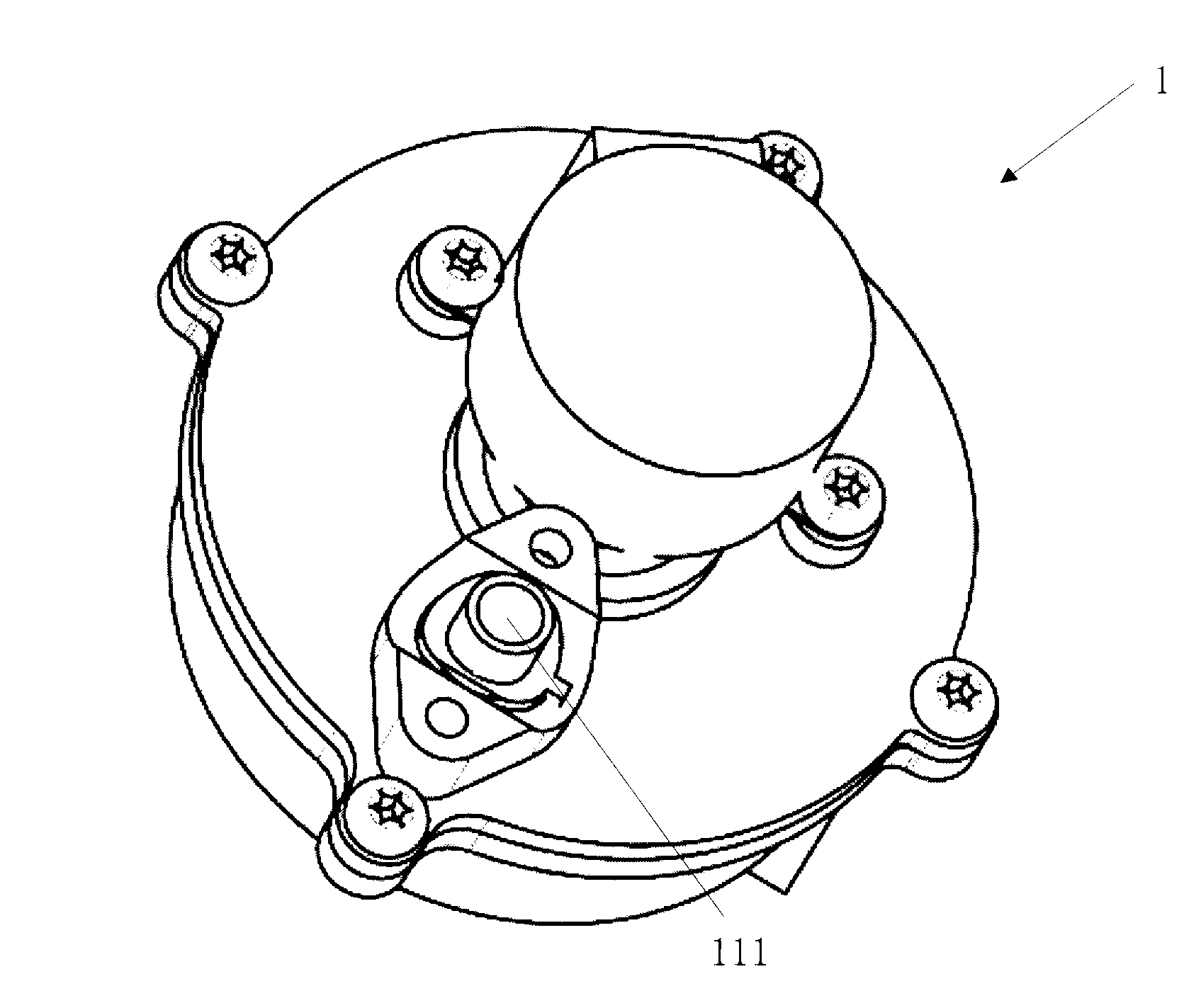
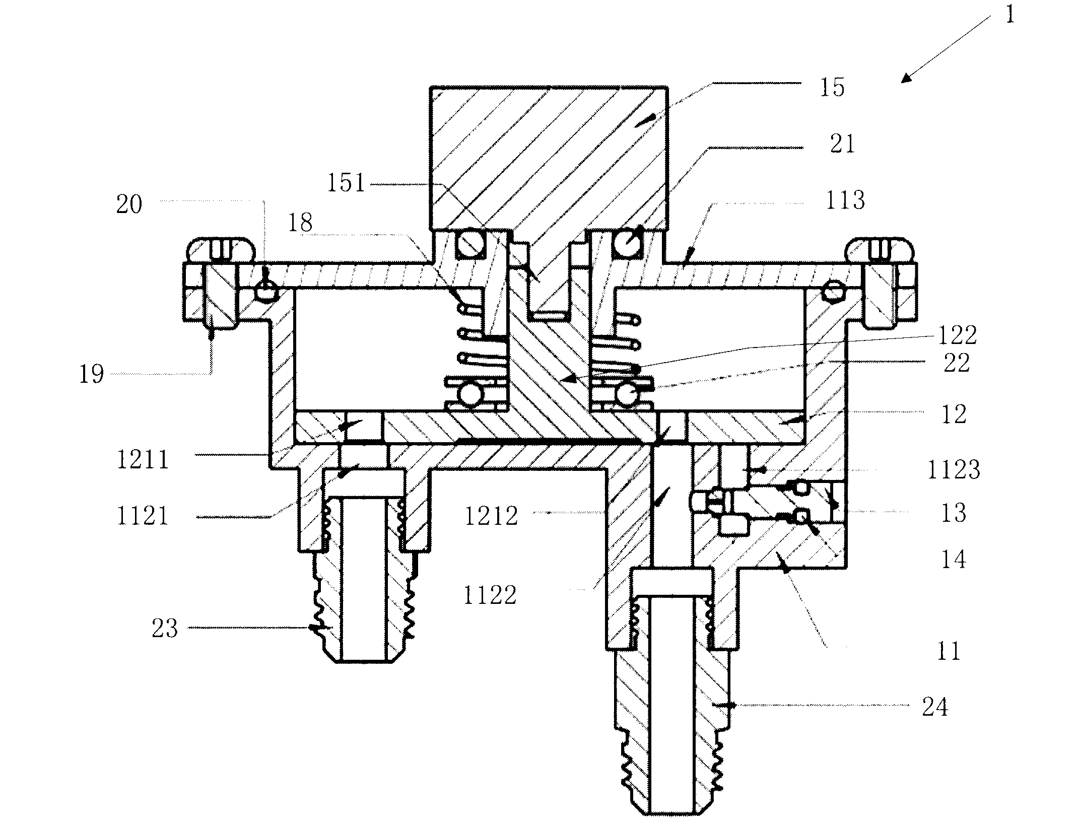
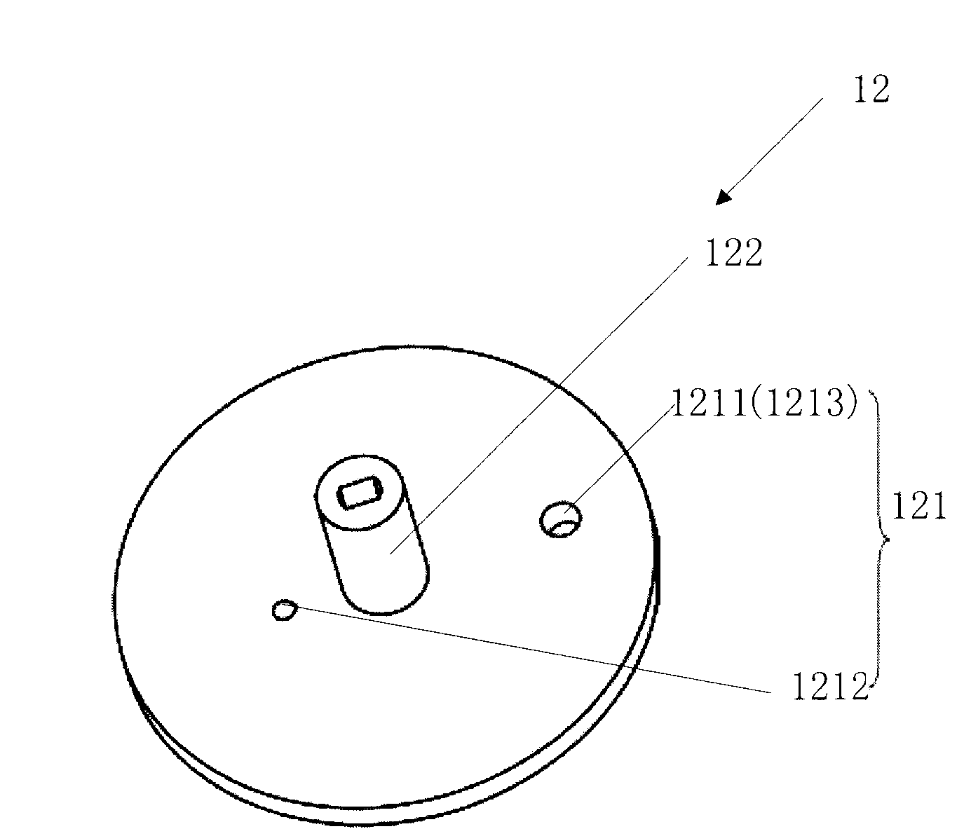
[0067] figure 1 It is a three-dimensional structural schematic diagram of an electrically controlled gas regulating valve 1 for a gas cooker provided by Embodiment 1 of the present invention, figure 2 yes figure 1 cutaway view of the structure, image 3 is a schematic diagram of the turntable structure.

[0068] combine figure 1 and figure 2 , the regulating valve 1 includes:

[0069] A valve body 11, the valve body 11 has an inner cavity and is provided with a gas inlet 111 and a gas outlet;

[0070] The turntable 12 that is in plane contact with the surface of the inner cavity of the valve body 11 and can rotate relative to the surface of the inner cavity of the valve body 11, the contact surface of the valve body 11 and the turntable 12 is tightly fitted; in addition, the turntable 12 has the function of selectively making the valve turn when it rotates. The gas outlet on the body 11 is connected with the inner chamber of the valve body 11 or disconnected or the con...

Embodiment 2

[0097] The difference between the second embodiment and the first embodiment is that in the gas regulating valve provided, the distances between the rotation center of the turntable 12 and the first gas outlet 1121 and the minimum fire inlet 1123 are set to be unequal. The structure of the turntable 12 that embodiment two provides is as Image 6 shown, combined with figure 2 , the distance between the rotation center of the turntable 12 and the first connecting channel 1211 and the third connecting channel 1213 is not equal. During the rotation of the turntable 12, the size of the overlapping area between the first gas outlet 1121, the second gas outlet 1122, and the minimum fire inlet 1123 and the first connecting channel 1211, the second connecting channel 1212, and the third connecting channel 1213 respectively can be changed. The degree of communication between the two gas outlets 1121 and 1122 and the inner cavity of the valve body 11 further achieves the purpose of con...

Embodiment 3

[0099] The difference between the third embodiment and the first and second embodiments is that there is no clear distinction between the inner and outer ring fires on some gas stoves, and the two fires are mixed, that is, only one fire is provided. For this kind of gas stove, this implementation The structure of the rotating disk 12 that example three provides is as Figure 7 As shown, only one connection channel 121 is provided. Similarly, the size of the overlapping area between the gas outlet and the connecting channel 121 can change the degree of communication between the gas outlet and the inner cavity of the valve body 11 , and can also achieve the purpose of controlling the gas in sections.


PUM


Abstract

A gas adjusting valve used for a gas stove comprises a valve body and a rotary disc which contacts the plane of the inner cavity surface of the valve body and rotates relative to the inner cavity surface of the valve body, wherein a gas inlet and a gas outlet are formed in the valve body. The valve body matches with the contact face of the rotary disc in a sealed mode. The rotary disc is provided with a connecting passage, and the connecting passage can selectively enable the gas outlet which is formed in the valve body to be connected or disconnected with the inner cavity of the valve body or change a connecting degree. The invention further provides an electric control gas adjusting valve used for the gas stove and the gas stove with the gas adjusting valve or the electric control gas adjusting valve. Due to the technical scheme, the problems that the existing gas stove adopts a plug valve which is inconvenient to manufacture and is high in cost can be avoided.

Description

technical field [0001] The invention relates to the technical field of gas stoves, in particular to a gas regulating valve for a gas stove, a gas stove including the regulating valve, a gas electric control gas regulating valve for a gas stove, and a gas regulating valve containing the electric control gas regulating valve. kitchen. Background technique [0002] Existing gas stoves generally control the size of the firepower through a cock valve, and the principle is to control the amount of gas flowing through the cock valve. The structure of the plug valve includes a valve body and a valve core, and the valve body and the valve core cooperate through a plug hole provided on the valve body. The valve body is also provided with an air inlet and an air outlet pipe; the valve core, whose cross-section is generally cylindrical or conical, has an air outlet hole in the axial direction. When the valve core rotates at different angles, the degree of connection between the air inl...

Claims


Application Information

Patent Timeline
Patent Type & Authority Applications(China)
IPC IPC(8): F16K11/074F16K27/04F16K31/04F24C3/12
CPCF16K11/074F23K2900/05002F16K3/08F23N1/005F23N2035/16F23N1/007F23K5/007F23N2035/24F23N2235/16F23N2235/24
Inventor 吴金花雷东多·何塞李兴洲
Owner BSH ELECTRICAL APPLIANCES JIANGSU
Why Eureka
Try Eureka