
Mechanically clamped turning tool for ring slot with stepped end surface

A technology of end faces and machine clamps, which is applied to the lathe tools, turning equipment, tool holder accessories, etc., can solve the problems that affect the production progress of the product, the difficulty of the tool head, and the serious breaking of the tool, so as to reduce the broken tool and improve the quality of the tool. The strength of the blade and the effect of speeding up the production process

Inactive Publication Date: 2015-05-13
KAIFENG AIR SEPARATION GROUP
View PDF7 Cites 0 Cited by
  • Summary
  • Abstract
  • Description
  • Claims
  • Application Information

AI Technical Summary

Problems solved by technology

[0002] Coal chemical gasifier membrane wall water channel uses a large number of orifice plate joints with similar structures, one of which has an annular groove on the step end surface of the orifice joint, and the lathe breaks seriously when cutting the groove, using ordinary welding turning tools, too much After all these efforts, the problem has been unable to be solved, which has seriously affected the production progress of the product.
However, when welding tools are used, it is difficult to manually grind out the inner and outer arc surfaces of the cutter head.

Method used


Image

  • Mechanically clamped turning tool for ring slot with stepped end surface
  • Mechanically clamped turning tool for ring slot with stepped end surface
  • Mechanically clamped turning tool for ring slot with stepped end surface

Examples


Embodiment Construction

[0017] The present invention will be further described below in conjunction with the accompanying drawings and specific embodiments.

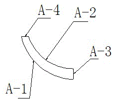
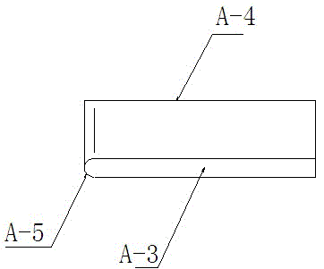
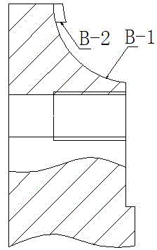
[0018] Such as figure 1 , 2 , As shown in 3 and 4, a step end face ring groove machine clamping tool includes a cutter head 1 and a cutter body 2, and the cutter head and cutter body are split structures. The cutter head is sickle-shaped, and the cutter head includes the inner arc surface A-1 of the cutter head, the outer arc surface A-2 of the cutter head, the rake face A-3, the bottom surface A-4 and the arc surface A-5 of the cutter head, Among them, the inner arc surface of the cutter head, the outer arc surface of the cutter head, the rake face and the bottom surface are all processed by wire cutting. The arc surface of the cutter head is manually ground and measured by the grinding sample; Interference occurs with the arc surface of the workpiece to be processed, and the width of the cutter head gradually narrows from the rake face to t...


PUM


Abstract

The invention relates to a mechanically clamped turning tool, in particular to a mechanically clamped turning tool for a ring slot with a stepped end surface, which is suitable for various porous plate joints of components in the coal chemical industry. The mechanically clamped turning tool comprises a turning tool head and a turning tool body, of which are of a separated structure; the turning tool head comprises a front turning tool surface, a bottom, a turning tool head inner arc surface and a turning tool head outer arc surface which are machined by a linear cutting manner, and the turning tool body comprises a turning tool inner arc surface and a turning tool body adhesion surface which are machined by the linear cutting manner; and the turning tool head outer arc surface is matched with the turning tool head inner arc surface, and the turning tool body adhesion surface is matched with the bottom of the turning tool head and is fixed by a pressing block and a compression screw in a mechanically clamping manner. According to the mechanically clamped turning tool for the ring slot with the stepped end surface, which is disclosed by the invention, the strength of a turning tool blade is improved by increasing the height of the turning tool head in a direction of the ring slot of a machined assembly and by assembling the turning tool in a mechanically clamping manner so that the turning tool is prevented from being damaged in a slot turning process.

Description

technical field [0001] The invention relates to a machine-clamped turning tool, in particular to a machine-clamped turning tool suitable for turning various "orifice joint" step end face ring grooves of coal chemical parts. Background technique [0002] Coal chemical gasifier membrane wall water channel uses a large number of orifice plate joints with similar structures, one of which has an annular groove on the step end surface of the orifice joint, and the lathe breaks seriously when cutting the groove, using ordinary welding turning tools, too much With such efforts, the problem has been unable to be solved, which has seriously affected the production schedule of the product. Because some orifice joints have very little space in the ring groove on the end face of the workpiece, in order to avoid interference between the flank of the turning tool and the surface of the processed workpiece, the relief angle of the turning tool must be increased, resulting in too small heigh...

Claims


Application Information

Patent Timeline
Patent Type & Authority Patents(China)
IPC IPC(8): B23B27/16
Inventor 徐纪高周礼新冷雪峰孟东民李艳马仁亮
Owner KAIFENG AIR SEPARATION GROUP
Learn More