Mixed bed structure of water treatment system

A water treatment system and mixed bed technology, applied in the field of water treatment, can solve problems such as poor precision and safety, slow resistance washing speed, troublesome installation, replacement and disassembly, etc., achieve high precision and safety, improve regeneration effect, Ease of installation and disassembly

Inactive Publication Date: 2013-06-12
江苏格朗瑞科技有限公司
View PDF4 Cites 5 Cited by
  • Summary
  • Abstract
  • Description
  • Claims
  • Application Information

AI Technical Summary

Problems solved by technology

However, the water cap is easy to fall off and deform when installed on the orifice plate, which affects the water distribution effect. It is troublesome to install, replace and disassemble, and the precision and safety are poor.
[0004] In addition, after the mixed bed works for a long time, the internal cation bed and yin bed will be saturated, and the deionized water cannot be effectively deionized. Therefore, it is necessary to regenerate the cation bed and the yin bed. The steps are backwashing, standing still, alkali absorption, slow washing, acid absorption, slow washing, quick washing, drainage, air mixing, final washing and other steps. Generally, the middle row of the mixed bed is set at the boundary between the positive bed and the negative bed. This setting method will lead to problems such as unsatisfactory regeneration effect of the yin bed and yang bed, slow resistance washing speed and short cycle.

Method used


Image

  • Mixed bed structure of water treatment system
  • Mixed bed structure of water treatment system

Examples


Embodiment Construction

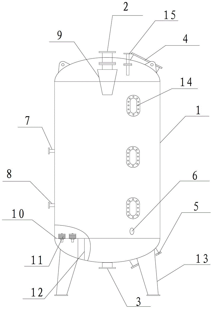
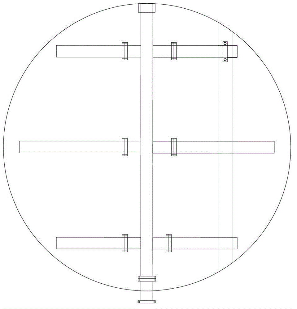
[0022] The traditional mixed bed is generally equipped with a water distribution device at its water inlet, which is an orifice plate with a water cap. Through the function of the water cap, the ionized water will fall evenly through the anion exchange resin and cation exchange resin in turn, and then be discharged through the water outlet. Enter the next processing procedure. The water cap is installed on the orifice plate, which is easy to fall off and deform, which affects the water distribution effect, and the installation, replacement and disassembly are more troublesome, and the precision and safety are poor. The regeneration effect of the yin bed and the yang bed is not ideal, and the resistance washing speed is slow and the cycle is short.

[0023] The present invention aims at the deficiencies in the prior art, and the present invention provides a mixed bed structure of a water treatment system to achieve a mixed bed that effectively solves the water distribution prob...


PUM

PropertyMeasurementUnit
thicknessaaaaaaaaaa
thicknessaaaaaaaaaa
thicknessaaaaaaaaaa

Abstract

The invention discloses a mixed bed structure of a water treatment system. The mixed bed structure comprises a cylindrical body, a water inlet formed in the upper part of the cylindrical body and a water outlet formed in the lower part of the cylindrical body, wherein anion exchange resin and cation exchange resin are arranged inside the cylindrical body, and the cylindrical body is further provided with charging holes and discharging holes; and an upper discharging device, a lower discharging device and a middle discharging device are further arranged inside the cylindrical body. The mixed bed structure further comprises a water distribution device which comprises a hanging basket, a pore plate and water caps, wherein the hanging basket is arranged below the water inlet, and the pore plate and the water caps are located above the water outlet. A pore plate and water caps, which are originally located at the water inlet, are replaced with the hanging basket, so that a uniform water distribution function of the water distribution device can be realized, and the leakage of the resin in a cylinder is prevented; and furthermore, the hanging basket can be conveniently mounted / dismounted and is higher in precision and safety, and the problem that the water distribution effect is affected by water cap falling can not exist. Meanwhile, the middle discharging device is arranged 5 cm above the cation exchange resin, so that the regeneration effect can be effectively improved, the resistance flushing is high in speed and long in cycle, and the engineering cost is lowered.

Description

technical field [0001] The invention relates to the technical field of water treatment, in particular to a mixed bed structure of a water treatment system. Background technique [0002] The mixed bed refers to the system in which water passes sequentially through the anion bed of the hydroxide type anion exchange resin and the cation bed of the hydrogen type cation exchange resin. Hydrogen-type cation exchange resin is used to remove cations in water; hydroxide-type anion-exchange resin is used to remove anions in water, and various mineral salts in water can be basically removed through the synchronous action of cation bed and anion bed. In order to obtain a better desalination effect, the positive bed is loaded with strong acid cation exchange resin, and the negative bed is generally loaded with strong base anion exchange resin. The mixed bed is also divided into internal synchronous regenerative mixed bed and external regenerative mixed bed. [0003] The traditional mixe...

Claims


Application Information

Patent Timeline
Patent Type & Authority Applications(China)
IPC IPC(8): C02F1/42
Inventor 张巍巍
Owner 江苏格朗瑞科技有限公司
Why Eureka
Try Eureka