Hydraulic device leakage measuring device

A technology for measuring devices and devices, which is applied to fluid pressure actuation devices, fluid pressure actuation system testing, and mechanical equipment, etc., can solve the problems of large overall changes to the equipment, increased costs, and difficulty in actual operation, and achieves simple and convenient operation. , the effect of low manufacturing cost

Active Publication Date: 2013-06-12
NANJING UNIV OF TECH +1
View PDF8 Cites 10 Cited by
  • Summary
  • Abstract
  • Description
  • Claims
  • Application Information

AI Technical Summary

Problems solved by technology

Real-time monitoring and detection will greatly change the overall equipment, and will add a considerable nu

Method used


Image

  • Hydraulic device leakage measuring device
  • Hydraulic device leakage measuring device
  • Hydraulic device leakage measuring device

Examples


Embodiment

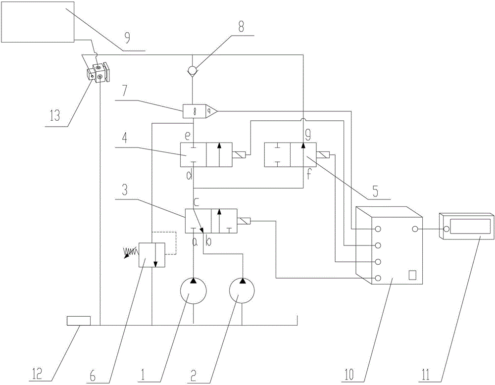
[0040] Such as Figure 1-8 As shown, this embodiment discloses a hydraulic valve leakage measurement device, including: figure 1 As shown, medium and high pressure pump 1, normal pressure low flow pump 2, three-way valve 3, first two-way valve 4, second two-way valve 5, overflow valve 6, flow sensor 7, one-way check valve 8, Measured hydraulic valve 9 , PLC controller 10 , electronic display 11 , fuel tank 12 , and second three-way valve 13 .

[0041] The three-way valve 3 has three outlets a, b, and c. When the outlet b of the three-way valve 3 communicates with the outlet c, the first two-way valve 4 is closed, that is, the outlets e and d are disconnected, and the second two-way valve 5 is opened, that is, the outlet g and f are connected, at this time, the hydraulic oil flows from the atmospheric pump through the three-way valve 3 into the second two-way valve 5; when the outlets a and c of the three-way valve 3 are connected, the first two-way valve 4 is closed, that is,...


PUM


Abstract

The invention discloses a hydraulic device leakage measuring device, which comprises an oil tank, a first hydraulic pump, a second hydraulic pump, a first three-way valve, a first two-way valve, a second two-way valve, a flow rate sensor and a second three-way valve, wherein the second three-way valve is used for connecting a hydraulic device, the two ends of the first three-way valve are inlets, another end is an outlet, the inlets at the two ends are either-or paths, one end of the second three-way valve is an inlet, the other ends are outlets, the outlets at the two ends are either-or paths, the oil tank is respectively connected with the two inlets of the first three-way valve through the first hydraulic pump and the second hydraulic pump via pipelines, the outlet of the first three-way valve is respectively connected with one end of the first two-way valve and the second two-way valve through pipelines after the flow division, the other end of the first two-way valve is connected with the flow rate sensor, is then communicated with the other end of the second two-way valve, and is connected with one inlet of the second three-way valve, and the two outlets of the second three-way valve are respectively connected with the hydraulic device and the oil tank.

Description

technical field [0001] The invention relates to the field of hydraulic equipment measurement, in particular to a hydraulic device leakage measurement device. Background technique [0002] Internal leakage is inevitable in hydraulic valves and other hydraulic components that require relative motion. Internal leakage will inevitably cause pressure loss inside the hydraulic valve. If the pressure loss is too large, it will cause a reduction in the execution efficiency of the hydraulic system. Harmful, it can form an oil film protective layer between components, play a role in lubrication, greatly reduce the resistance of working movement, and minimize wear. Therefore, the internal leakage of hydraulic valves and other components needs to be determined through experiments to keep the leakage within an allowable range. [0003] Therefore, either real-time monitoring and detection of various hydraulic valves and other components must be performed, or single-item detection must b...

Claims


Application Information

Patent Timeline
IPC IPC(8): F15B19/00
Inventor 殷晨波贾文华叶仪
Owner NANJING UNIV OF TECH
Why Eureka
Try Eureka