
Touch control display device

A technology of a touch display device and a display module, which is applied in the direction of instruments, electrical digital data processing, and input/output process of data processing, etc., and can solve problems such as high energy consumption, affecting sensing sensitivity, and affecting display quality

Inactive Publication Date: 2013-06-12
AU OPTRONICS CORP
View PDF4 Cites 15 Cited by
  • Summary
  • Abstract
  • Description
  • Claims
  • Application Information

AI Technical Summary

Problems solved by technology

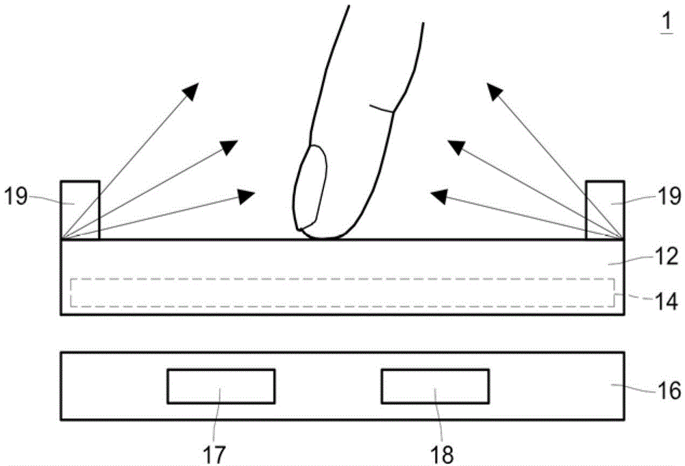
[0004] In the existing touch display device 1, the infrared light needs to pass through the display device 12 to reach the touch sensing layer 14 after being reflected by the finger, which may cause the attenuation of the infrared light and affect the sensing sensitivity.
However, in order to improve the sensitivity, the luminance of the infrared light source 17 is strengthened to cause the problem of high energy consumption.
In addition, in the existing touch display device 1, the white light source 18 is arranged on the side of the light guide plate 16, and the viewing angle of the white light source 18 on the display plane (ie, the touch plane) of the display device is likely to be too small, which affects the display. quality

Method used


Image

  • Touch control display device
  • Touch control display device
  • Touch control display device

Examples


Embodiment Construction

[0057] The present invention is described in detail below with reference to the accompanying drawings and specific embodiments, but is not intended to limit the present invention.

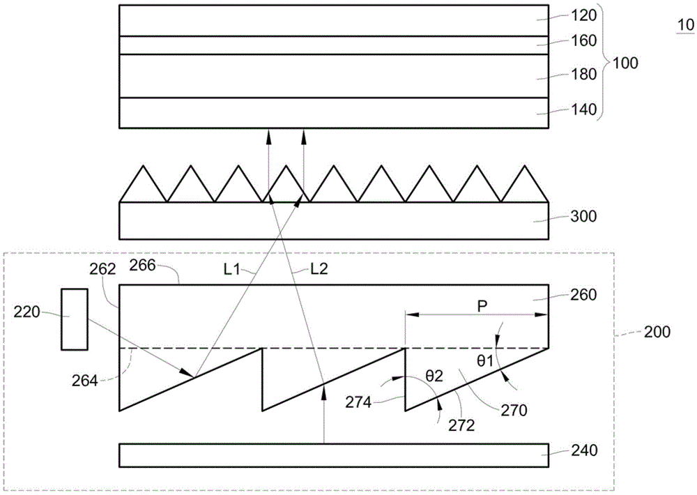
[0058] Please refer to figure 2, the second is a side view of the touch display device 10 according to an embodiment of the present invention. In this embodiment, the touch display device 10 includes a display module 100 , a backlight module 200 and a prism sheet 300 , wherein the prism sheet 300 is disposed between the display module 100 and the backlight group 200 . The display module 100 has a touch sensing layer 160 . Specifically, the display module 100 has an upper substrate 120 , a lower substrate 140 and a display medium layer 180 , and the touch sensing layer 160 is disposed on the upper substrate 120 and sandwiched between Between the upper substrate 120 and the lower substrate 140 is an in-cell touch display module. The in-cell touch display module 100 can reduce the overall thickness...


PUM


Abstract

The invention relates to a touch control display device comprising a display module, a backlight module and a prismatic lens. The display module comprises a touch control sensing layer. The backlight module comprises a first light source, a second light source and a light guide plate. The first light source has a first wavelength and the second light source has a second wavelength which is less than the first wavelength. The light guide plate comprises a first incident light surface, a second incident light surface and an emergent light surface. The second incident light surface faces the emergent light surface and the first incident light surface is connected with the second incident light surface and the emergent light surface. The first light source is disposed on the first incident light surface and the second light source is disposed on the second incident light surface. The prismatic lens is disposed between the display module and the backlight module. According to the invention, the sensitivity of touch control is improved.

Description

technical field [0001] The present invention relates to a touch display device, in particular to a high sensitivity touch display device. Background technique [0002] Due to the characteristics of human-computer interaction, touch display devices have gradually replaced traditional buttons or keyboards, and are widely used in various electronic products, such as smart phones, tablet PCs, digital cameras, and Notebook PC. [0003] figure 1 For a side view of the existing touch display device 1, please refer to figure 1 The touch display device 1 includes a display device 12 , a touch sensing layer 14 , a light guide plate 16 , infrared light sources 17 and 19 and a white light source 18 , wherein the touch sensing layer 14 is disposed in the display device 12 . The infrared light source 17 is disposed on the side of the light guide plate 16 to provide touch sensing. Specifically, the infrared light source 17 guides the infrared light source to the touch surface of the dis...

Claims


Application Information

Patent Timeline
Patent Type & Authority Applications(China)
IPC IPC(8): G06F3/042
Inventor 牛慈伶范富诚
Owner AU OPTRONICS CORP
Learn More