A kind of backlight dimming circuit and its dimming method, liquid crystal display

A dimming circuit and backlight technology, applied in static indicators, instruments, etc., can solve the problems of complex algorithm and timing control, increase the cost of the whole machine, etc., to reduce backlight power consumption, promote energy saving, and reduce data conversion and data. The effect of transmission

Active Publication Date: 2015-08-26
CHANGSHA HKC OPTOELECTRONICS CO LTD
View PDF7 Cites 0 Cited by
  • Summary
  • Abstract
  • Description
  • Claims
  • Application Information

AI Technical Summary

Problems solved by technology

This solution also requires hardware support such as MCU, and the more partitions, the more LED drivers are used, and the more complex the algorithm and timing control, which greatly increases the cost of the whole machine

Method used


Image

  • A kind of backlight dimming circuit and its dimming method, liquid crystal display
  • A kind of backlight dimming circuit and its dimming method, liquid crystal display

Examples


Embodiment 1

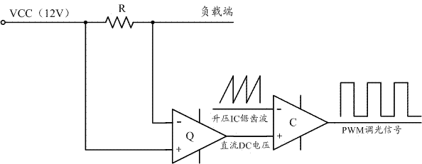
[0034] Specifically, a backlight dimming circuit according to an embodiment of the present invention includes:

[0035] The power supply voltage terminal VCC is used to provide a power supply voltage;

[0036] Operational amplifier Q, its non-inverting input terminal is connected to the power supply voltage terminal VCC, and its inverting input terminal is connected to the load terminal;

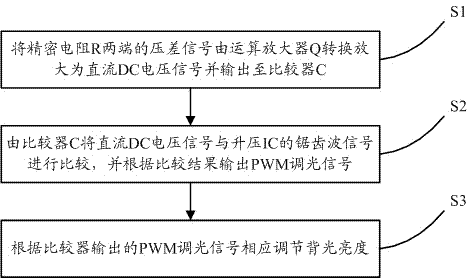
[0037] The precision resistor R is connected between the non-inverting input terminal and the inverting input terminal of the operational amplifier Q, and the voltage difference signal across the precision resistor R is converted and amplified by the operational amplifier Q into a DC voltage signal and output;

[0038] Comparator C, its non-inverting input terminal receives the DC voltage signal output by the operational amplifier Q, and its inverting input terminal receives the sawtooth signal from the boost IC in the boost converter, which is used to combine the DC voltage signal with the ...


PUM


Abstract

A backlight dimming circuit, a dimming method thereof and a liquid crystal display. The backlight dimming circuit comprises: a power supply voltage end (VCC) that is used for providing power supply voltage; an operational amplifier (Q), wherein a non-inverting input end thereof is connected to the power supply voltage end (VCC), and an inverting input end is connected to a load end; a precision resistor (R) that is connected between the non-inverting input end and the inverting input end of the operational amplifier (Q), wherein a voltage difference signal at two ends of the precision resistor (R) is converted and amplified into a direct current (DC) voltage signal and output by the operational amplifier (Q); and a comparator (C), wherein a non-inverting input end thereof receives the DC voltage signal output by the operational amplifier (Q), and an inverting input end receives a saw-tooth wave signal of a boost (IC) from a boost converter, and the comparator is used for comparing the DC voltage signal with the saw-tooth wave signal of the boost (IC) and output a PWM dimming signal according a comparison result. The backlight dimming circuit is simple in structure, and is lower in cost input. Backlight brightness is associated with an image in real time, reducing backlight power consumption, and promoting energy economization of a product.

Description

technical field [0001] The invention relates to the field of image display, in particular to a backlight dimming circuit, a dimming method thereof, and a liquid crystal display. Background technique [0002] At present, the main theme of the industry is green energy saving and environmental protection. Large-size LCD monitors especially need to be energy-saving. Taking 48 inches as an example, the power of the whole machine is 120W, of which the power of the backlight is about 60W, accounting for 50% of the power of the whole machine. Therefore, the energy saving of the backlight will play an important role in the green and energy-saving products. At present, there are many technologies to realize energy saving by adjusting the brightness of the backlight in various ways. [0003] The first is manual dimming, that is, the user manually adjusts through the operation menu. This solution is not smart, and manual adjustments lead to cumbersome operations; in addition, because ...

Claims


Application Information

Patent Timeline
Patent Type & Authority Patents(China)
IPC IPC(8): G09G3/36G09G3/34
CPCG09G2320/064G09G3/36G09G2330/02G09G3/34
Inventor 杨翔陈辛洪
Owner CHANGSHA HKC OPTOELECTRONICS CO LTD
Why Eureka
Try Eureka