Multi-chip integrated e-band receiver module

A multi-chip integration and receiving module technology, applied in electrical components, transmission systems, etc., can solve the problems of complex system circuits, low integration of millimeter wave modules, and large volume, and achieve good port performance, compact structure, and high integration Effect

Active Publication Date: 2015-10-07
SOUTHEAST UNIV
View PDF4 Cites 0 Cited by
  • Summary
  • Abstract
  • Description
  • Claims
  • Application Information

AI Technical Summary

Problems solved by technology

It realizes the down-conversion function from E-band to X-band in one module, which can overcome the disadvantages of low integration of millimeter-wave modules, complex system circuits, and large volume in the prior art.

Method used


Image

  • Multi-chip integrated e-band receiver module
  • Multi-chip integrated e-band receiver module
  • Multi-chip integrated e-band receiver module

Examples


Embodiment Construction

[0026] In the following, the present invention will be further clarified with reference to specific examples. It should be understood that these examples are only used to illustrate the present invention and not to limit the scope of the present invention. After reading the present invention, those skilled in the art will understand various equivalent forms of the present invention. All the modifications fall within the scope defined by the appended claims of this application.

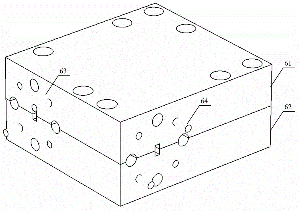
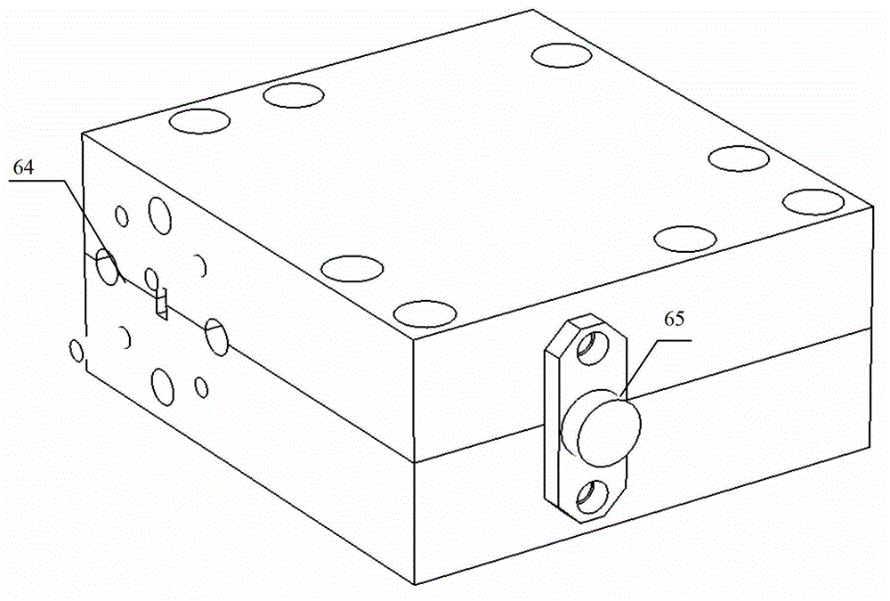
[0027] Such as figure 2 , image 3 , Figure 4 with Figure 5 As shown, this embodiment includes a metal upper base 61 and a metal lower base 62. The cavity formed by the metal upper base 61 and the metal lower base 62 is respectively provided with a first part of SMA to microstrip transition 1 and an intermediate frequency low-pass filter circuit. 2. The first circuit for short; the local oscillator circuit, including the local oscillator amplifier chip 4, the microstrip waveguide transition structure 42...


PUM


Abstract

The invention discloses a multi-chip integration E band receiving module which comprises an upper metal base and a lower metal base, a medium-frequency low-pass filtering circuit, and a local oscillator circuit and a down-conversion structure are respectively arranged in a cavity formed by the upper metal base and the lower metal base. A medium-frequency input end adopts a standard subminiature version A (SMA) connector, a local oscillator input end is of a standard waveguide flange structure, and the radio frequency output end is of a standard waveguide flange structure. Signal coupling between the waveguide and microstrip circuits of the module is achieved through a transitional structure, and a low-loss substrate circuit is connected with various functional gallium arsenide chips electrically. Based on the multi-chip integration technology, the multi-chip integration E band receiving module has the advantages of being compact in structure, high in integration degree, low in cost, good in consistency and convenient to manufacture in a large-scale mode.

Description

Technical field [0001] The present invention relates to the field of wireless communication technology, in particular to a multi-chip integrated E-band receiving module. Background technique [0002] Microwave is a common wireless communication technology. It is widely used in the relay and backhaul of various communication systems due to its long-distance, large-capacity, fast deployment, and strong anti-loss characteristics. With the continuous demand for mobile broadband, the conventional 6GHz~38GHz microwave spectrum resources have been quickly exhausted, and the expansion of microwave communication to higher frequency bands has become an inevitable trend. E-band microwaves were released by the International Telecommunication Union (ITU-R) in 2001 and 2003. They mainly include high-frequency microwave communications at 60GHz and 80GHz. The 60GHz free frequency band was earlier used by military and industrial customers. For businessmen, the 80GHz microwave frequency band will...

Claims


Application Information

Patent Timeline
Patent Type & Authority Patents(China)
IPC IPC(8): H04B1/16
Inventor 杨非王宗新孟洪福崔铁军孙忠良
Owner SOUTHEAST UNIV
Why Eureka
Try Eureka