Method for producing slit material

A manufacturing method and slit technology, applied in the direction of manufacturing tools, knives for shearing machines, shearing devices, etc., can solve the problems of waste, large materials, losses, etc., and achieve the effect of suppressing material costs and preventing bad shapes

Inactive Publication Date: 2013-06-12
MITSUBISHI ELECTRIC CORP +1
View PDF13 Cites 0 Cited by
  • Summary
  • Abstract
  • Description
  • Claims
  • Application Information

AI Technical Summary

Problems solved by technology

[0007] However, there is a problem that a large material loss occurs because the trimmed part or the strip will be wasted.

Method used


Image

  • Method for producing slit material
  • Method for producing slit material
  • Method for producing slit material

Examples


Embodiment approach 1

[0033] FIG. 1 is a front view illustrating a method of manufacturing a slit material according to Embodiment 1 of the present invention. Fig. 2 is a sectional view along A-A' direction in Fig. 1, and Fig. 3 is a sectional view along B-B' direction in Fig. 1 . Fig. 4 is a plan view showing a slit material according to Embodiment 1 of the present invention.

[0034] First, as shown in Figures 1 to 3, the first and second circular blades 10, 12, which are arranged transversely and have a plurality of rectangular blades in cross-section, face each other, and each blade of the first circular blade 10 is positioned relative to the first circular blade 10. The corresponding blades of the 2 circular blades 12 are arranged so as to be shifted to the same side in the lateral direction.

[0035] Then, by the guide roller 14, the metal strip 16 is introduced from the side closer to the first round blade 10 than the second round blade 12, so that the metal strip 16 is wound on the second ...

Embodiment approach 2

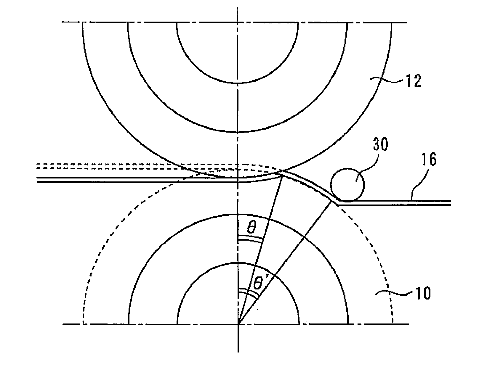
[0046] FIG. 10 is a front view illustrating a method of manufacturing a slit material according to Embodiment 2 of the present invention. Fig. 11 is a sectional view along the A-A' direction in Fig. 10, and Fig. 12 is a sectional view along the B-B' direction in Fig. 10 . In this embodiment, a guide roller 30 is provided on the entrance side of the first and second round blades 10 and 12 . Then, the metal strip 16 is wound around the first circular blade 10 by pressing the metal strip 16 against the first circular blade 10 with the guide roller 30 before cutting the metal strip 16 .

[0047]Thus, the slit strain of the first edge portion 20 of the slit material 18 is smaller (substantially zero) than the slit strain of the second edge portion 22 . Therefore, similarly to Embodiment 1, material costs can be suppressed, and shape defects due to slit strain can be prevented.

Embodiment approach 3

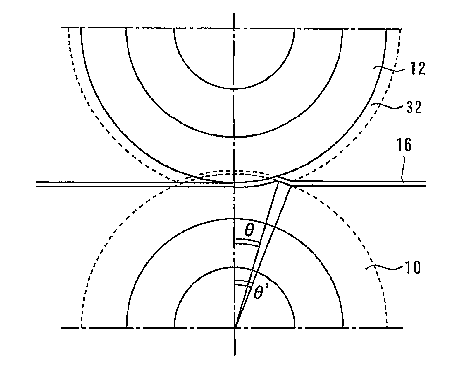
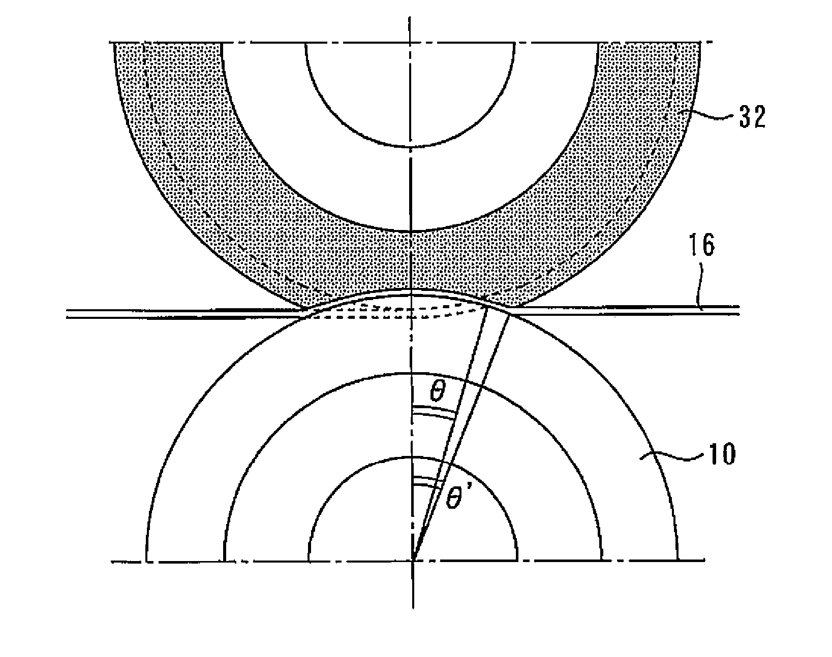
[0049] 13 is a front view for explaining a method of manufacturing a slit material according to Embodiment 3 of the present invention. Fig. 14 is a sectional view along the A-A' direction in Fig. 13, and Fig. 15 is a sectional view along the B-B' direction in Fig. 13 . In this embodiment, the rubber ring 32 is provided on the lateral side of the first round blade 10 so as to face the first round blade 10 . And when the metal strip 16 is cut, the metal strip 16 is pressed against the first circular blade 10 with the rubber ring 32 .

[0050] Thus, the slit strain of the first edge portion 20 of the slit material 18 is smaller (substantially zero) than the slit strain of the second edge portion 22 . Therefore, similarly to Embodiment 1, material costs can be suppressed, and shape defects due to slit strain can be prevented.


PUM


Abstract

First and second round blades 10 and 12 each having a plurality of laterally arranged blades of rectangular section are opposed to each other, and each blade of the first round blade 10 is disposed so as to be displaced laterally to the same side of the corresponding blade of the second round blade 12. Subsequently, a metal strip 16 is wound around the first round blade 10 without contacting the second round blade 12. Subsequently, while the metal strip 16 is being pressed to the first round blade 10, the metal strip 16 is bitten into the rotating first and second round blades 12 and thereby sheared. Accordingly, a slit material 18 having a predetermined width is formed.

Description

technical field [0001] The present invention relates to a method of manufacturing a slit material capable of suppressing material costs and preventing shape defects caused by slit strain. Background technique [0002] The metal strip is formed into a slit material with a predetermined width, and punched by a punching machine. For forming the slit material, a tool in which two circular blades having a rectangular cross section are laterally shifted is used. The two rotating circular blades bite into the belt plate to cut it, thereby forming a slit material with a specified width. [0003] After cutting, the belt plate is used for direction conversion. At this time, the edge of the slit material is subject to a large strain due to being restrained by the circular blade, and plastic deformation will occur. As a result, stress called slit strain remains at the edge of the slit material. [0004] If the slit material with the slit strain remaining is punched with a punching m...

Claims


Application Information

Patent Timeline
Patent Type & Authority Applications(China)
IPC IPC(8): B23D19/06B21D28/00
CPCB23D19/04B23D35/001B21D28/00B23D19/06
Inventor 中井大
Owner MITSUBISHI ELECTRIC CORP
Why Eureka
Try Eureka