Machining device

A technology for processing equipment and processing fluids, which can be applied to combined equipment, electrical components, and dispersed particle separation. cost effect

Active Publication Date: 2015-06-03
DISCO CORP
View PDF7 Cites 0 Cited by
  • Summary
  • Abstract
  • Description
  • Claims
  • Application Information

AI Technical Summary

Problems solved by technology

[0005] However, the purification room used in the semiconductor device manufacturing process passes through the HEPA filter (High Efficiency Particulate Air Filter: High Efficiency Particulate Air Filter), ULPA filter (Ultra Low Penetration Air Filter: Ultra Low Penetration Air Filter), etc. The high-performance filter takes in outside air and keeps the temperature inside the clean room constant, so there is a problem that the operating cost of the clean room is high
In addition, there is a problem that the cost of exhausting the mist out of the clean room is also high, and the equipment cost of the clean room is high.

Method used


Image

  • Machining device
  • Machining device
  • Machining device

Examples


Embodiment Construction

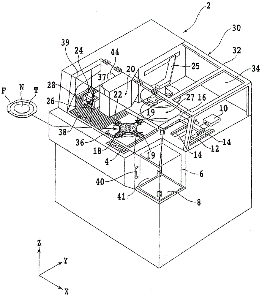
[0034] Hereinafter, embodiments of the present invention will be described in detail with reference to the drawings. refer to figure 1 , shows an external perspective view of a cutting device (scribing device) 2 according to the first embodiment of the present invention, which is one type of processing device. On the front side of the cutting device 2, an operation panel 4 for an operator to input instructions to the device such as machining conditions is provided.

[0035] The wafer W to be cut is attached to a dicing tape T as an adhesive tape, and the outer peripheral portion of the dicing tape T is attached to an annular frame F. As shown in FIG. As a result, the wafer W is supported by the ring frame F via the dicing tape T, and a plurality of (for example, 25) wafers are accommodated in the wafer cassette 6 . The wafer cassette 6 is placed on a cassette elevator 8 capable of moving up and down.

[0036] Arranged behind the wafer cassette 6 is an unloading and loading ...


PUM


Abstract

The invention provides a machining device, which can reduce the running cost on a cleaning room and facilities. The machining device comprises a clamping workbench for holding objects to be machined; a machining mechanism used for machining objects while supplying machining liquid at the same time; and a casing for covering the clamping workbench and the machining mechanism. The machining device is characterized by being provided with a mist machining unit for machining mists. The mist machining unit consists of a pumping pipeline and a mist removal mechanism .The pumping pipeline is connected with the interior of the casing and is used for pumping mists generated during the machining process. The mist removal mechanism is connected with the pumping pipeline and is used for removing mists from air. The mist removal mechanism consists of an anti-mist unit and a fan unit.

Description

technical field [0001] The present invention relates to processing devices such as cutting devices and grinding devices installed in a clean room. Background technique [0002] For semiconductor wafers with multiple devices such as IC (Integrated circuit) and LSI (Large Scale Integration: Large Scale Integration) formed on the surface divided by the planned division line, the back surface is ground by a grinding device and processed into a predetermined shape. After a certain thickness, use a dicing device (cutting device) to cut along the predetermined dividing line and divide it into individual devices. The divided devices are widely used in electrical equipment such as mobile phones and personal computers. [0003] Processing devices such as a grinding device and a dicing device are installed in a clean room, and processing is performed while supplying a processing fluid during processing of a wafer. Therefore, mist is generated by processing of wafers, and an exhaust de...

Claims


Application Information

Patent Timeline
Patent Type & Authority Patents(China)
IPC IPC(8): B01D50/00H01L21/67
Inventor 藤田敦史吉田干
Owner DISCO CORP
Why Eureka
Try Eureka