
Vehicle brake system for a motor vehicle and method for controlling the vehicle brake system when the parking brake function is released

A technology of vehicle braking and function, which is applied in the field of vehicle braking system and can solve problems such as discomfort

Active Publication Date: 2015-10-21
LUCAS AUTOMOTIVE GMBH
View PDF7 Cites 0 Cited by
  • Summary
  • Abstract
  • Description
  • Claims
  • Application Information

AI Technical Summary

Problems solved by technology

What the driver feels about this is a sudden release of the parking brake, which can be uncomfortable during a start, especially if the start is done downhill

Method used


Image

  • Vehicle brake system for a motor vehicle and method for controlling the vehicle brake system when the parking brake function is released
  • Vehicle brake system for a motor vehicle and method for controlling the vehicle brake system when the parking brake function is released
  • Vehicle brake system for a motor vehicle and method for controlling the vehicle brake system when the parking brake function is released

Examples


Embodiment Construction

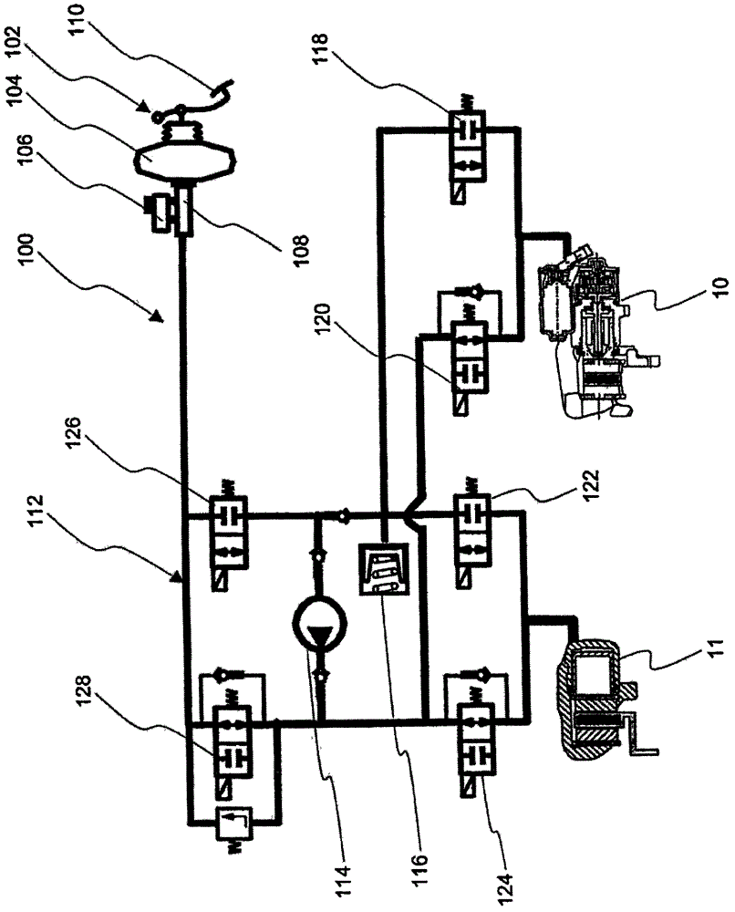
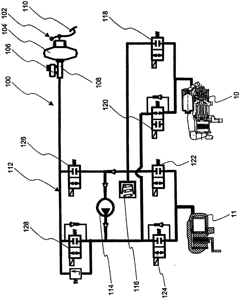
[0022] figure 1 A circuit diagram for a vehicle brake system 100 according to the invention is schematically shown. The vehicle brake system comprises a pressure source 102 which is designed with a brake booster 104 , a storage tank 106 , a master brake cylinder 108 and a brake pedal 110 actuatable by the driver. The pressure source 102 is in hydraulic communication with a hydraulic brake circuit 112 . The hydraulic brake circuit has a motor-controllable pump 114 and a pressure accumulator 116 . One also sees two disc brakes, namely a disc brake 10 for the rear wheel and a disc brake 11 for the front wheel.

[0023] Each disc brake 10, 11 is provided with a plurality of valves 118, 120, 122, 124 controllable by control means (not shown). Also visible are inlet valves 126 and 128 , which allow hydraulic brake circuit 112 to be hydraulically disconnected from driver-operable pressure source 102 .

[0024] As far as the service brake function is concerned, the schematically s...


PUM


Abstract

A vehicle brake system having a hydraulically actuable disc brake device which has an electromechanical actuating device for activating a parking brake function, wherein the vehicle brake system has a hydraulic circuit with a hydraulic pressure source and actuable hydraulic functional elements, in order to hydraulically actuate the disc brake device in accordance with a service brake action of a driver or an automatic activation of a driving assistance system, wherein, furthermore, the vehicle brake system has a control device, in order to actuate the electromechanical actuating device in accordance with a parking brake action of the driver or an automatic activation of the parking brake function. In order to avoid abrupt release of the parking brake function, it is provided here that the control device is configured for actuating at least one of the hydraulic functional elements in such a way that, in order to release the parking brake function, a hydraulic fluid volume is isolated in the disc brake device by actuation of the electromechanical actuating device and the hydraulic fluid volume can be used to generate a predefined hydraulic pressure hydraulically during the release of the parking brake function by means of the electromechanical actuating device.

Description

technical field [0001] The invention relates to a vehicle brake system having a hydraulically controllable disc brake with an electromechanical operating device for activating the parking brake function, wherein the vehicle brake system has a hydraulic pressure source and a plurality of A hydraulic circuit of controllable hydraulic functional parts for hydraulically controlling the disc brake according to the driver's service brake action or according to automatic activation, wherein the vehicle brake system also has a control device for according to the driver The parking brake action or according to the automatic activation of the parking brake function to control the electromechanical operating device. The invention also relates to a method for controlling a vehicle brake system of the type described above. Background technique [0002] Various vehicle braking systems are known from the prior art. Document DE 10 2005 051 082 A1 describes in detail a vehicle brake system...

Claims


Application Information

Patent Timeline
Patent Type & Authority Patents(China)
IPC IPC(8): B60T13/58B60T13/74F16D55/226F16D65/14B60T7/08
CPCB60T13/588B60T7/042B60T8/32B60T13/662B60T13/741B60T13/746F16D55/226F16D65/18F16D2121/02F16D2121/24F16D2123/00
Inventor 迈克尔·施瓦茨H·施密特
Owner LUCAS AUTOMOTIVE GMBH
Learn More