Vehicle

a technology for transmission systems and vehicles, applied in mechanical devices, gearing details, gearing, etc., can solve the problems of short durability of belts, inability to brake engines, belt slippage, etc., and achieve the effect of increasing the clutch pressure, preventing sudden acceleration of vehicles, and increasing the clutch pressur

Active Publication Date: 2009-10-13
KANZAKI KOKYUKOKI MFG
View PDF14 Cites 18 Cited by
  • Summary
  • Abstract
  • Description
  • Claims
  • Application Information

AI Technical Summary

Benefits of technology

[0011]Due to either the first or second aspect of the invention, the multi-speed transmission ensures performance of a smooth speed change (gearshift) without cease of power transmission from the engine to the axle. Therefore, the multi-speed transmission does not require the conventional CVT, so that the multi-speed transmission is safe from the problems peculiar to the CVT. That is, the multi-speed transmission has no problem of the belt slipping when wet, has satisfactory durability, and enables an effective engine braking action. Further, the sole multi-speed transmission does not have to be combined with another transmission mechanism, thereby being simple and inexpensive and facilitating maintenance.
[0034]Preferably, when a tilt angle of the vehicle descending a slope is detected, the increased rate of the clutch pressure is smaller than that when both a tilt angle of the vehicle traveling on a flat land and a small weight of the vehicle are detected. Therefore, when the vehicle descends a slope, the clutch pressure of the start-up clutch and the driving force of the axle are increased slowly so as to prevent sudden acceleration of the vehicle.

Problems solved by technology

However, the CVT has peculiar disadvantages, such as slipping of the belt when wet, short durability of the belt, and inability of engine braking.
However, there still exists the problem that the alternative multi-speed transmission cannot ensure a proper sufficient traveling performance for a vehicle because disengagement of its clutch for gearshift causes a cut-off of the power transmission to the axle, which may cause unexpected movement of a vehicle traveling on a slope.
However, if the gearshift timing relative to an actual traveling speed of the vehicle, i.e., an actual rotary speed of the axle, is simply fixed, a vehicle ascending a slope or having a heavy weight may have an engine stop because a shift-up timing occurs too early to ensure acceleration of the vehicle, or a vehicle descending a slope may be unexpectedly accelerated because a shift-down timing occurs too late to prevent acceleration of the vehicle so as to void an engine braking, i.e., cause an inertial gravity force of the descending vehicle to overcome the engine braking force.

Method used


Image

  • Vehicle
  • Vehicle
  • Vehicle

Examples


first embodiment

[0073]Referring to FIGS. 1 to 9, a utility vehicle will be described. Hereinafter, the position and direction of each element is stated on the basis of the traveling direction of the vehicle.

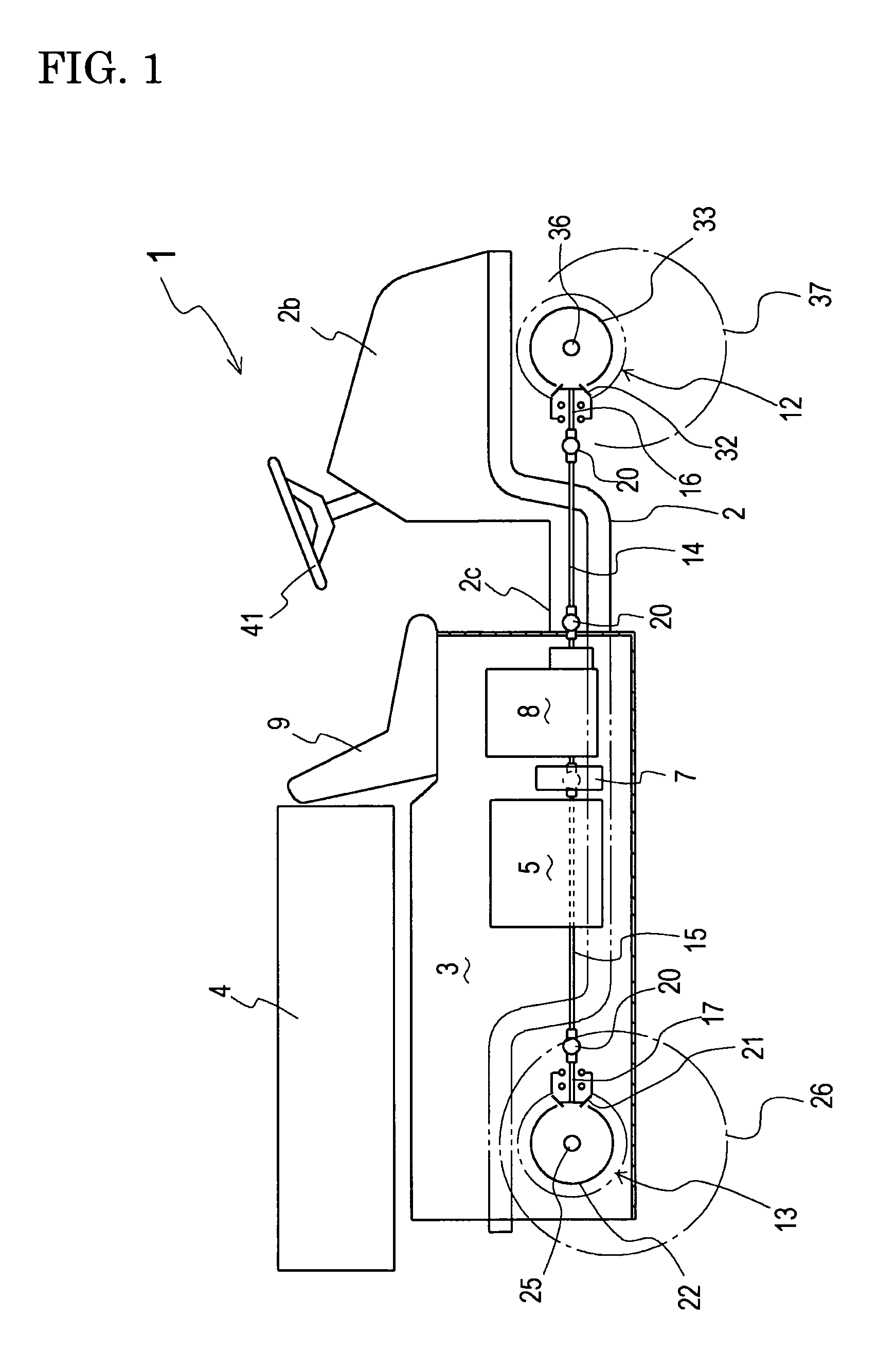
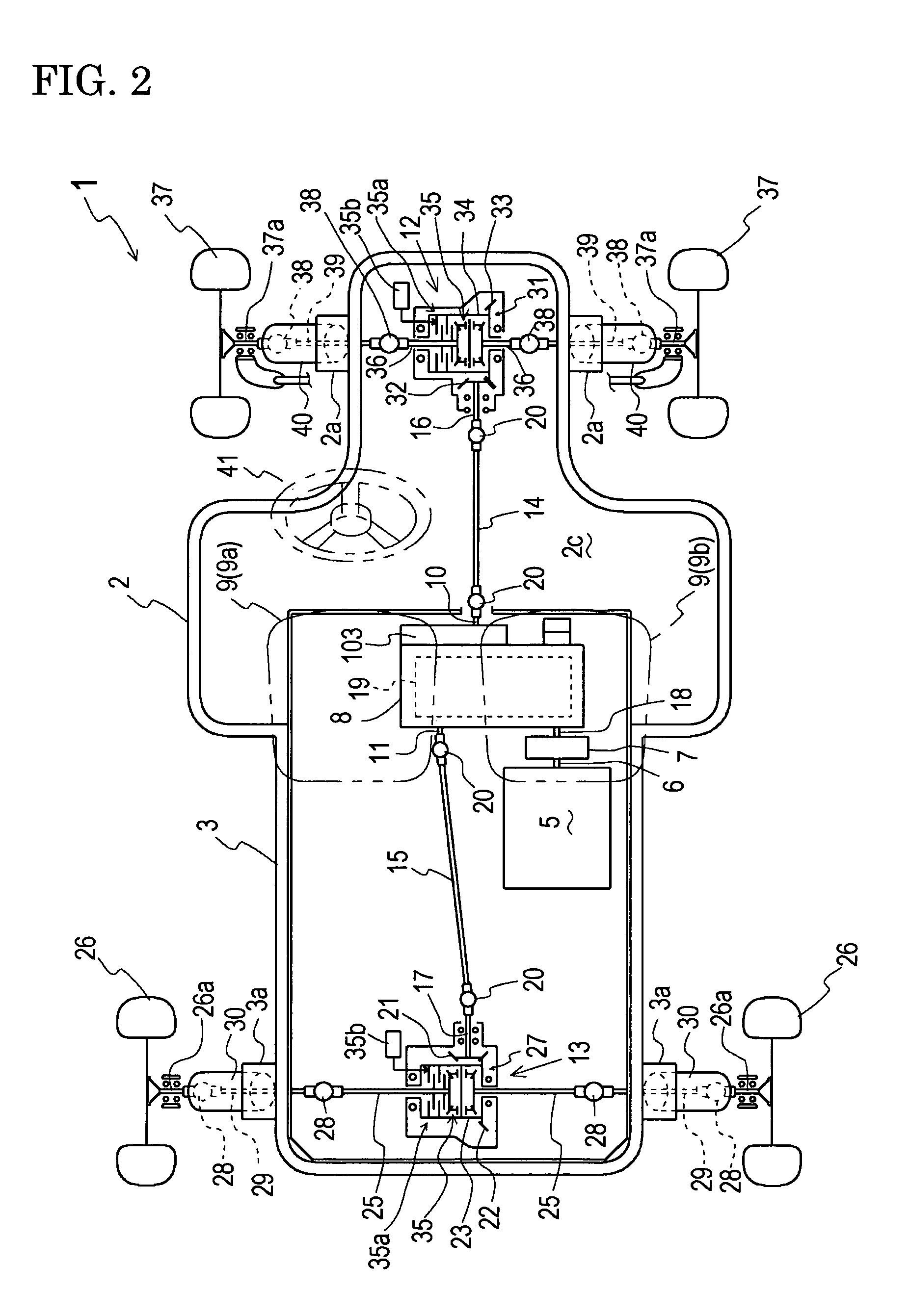
[0074]A general structure of a utility vehicle 1 will be described with reference to FIGS. 1 and 2. A front frame 2 and a rear frame 3 joined to each other constitute an entire body frame of utility vehicle 1. Rear frame 3 consists of a horizontal bottom plate, which is substantially rectangular when viewed in plan, and vertical side plates erected on front, rear, left and right end edges of the bottom plate. A cargo 4 is disposed above rear frame 3. Preferably, cargo 4 is vertically rotatable. Rear frame 3 serves as a base for supporting cargo 4. A pair of left and right seats 9 are mounted on a downwardly stepped front portion of rear frame 3. One seat 9 (in this embodiment, left seat 9) is a driver's seat 9a, and the other seat 9 (in this embodiment, right seat 9) is a partner's seat 9b. A s...

third embodiment

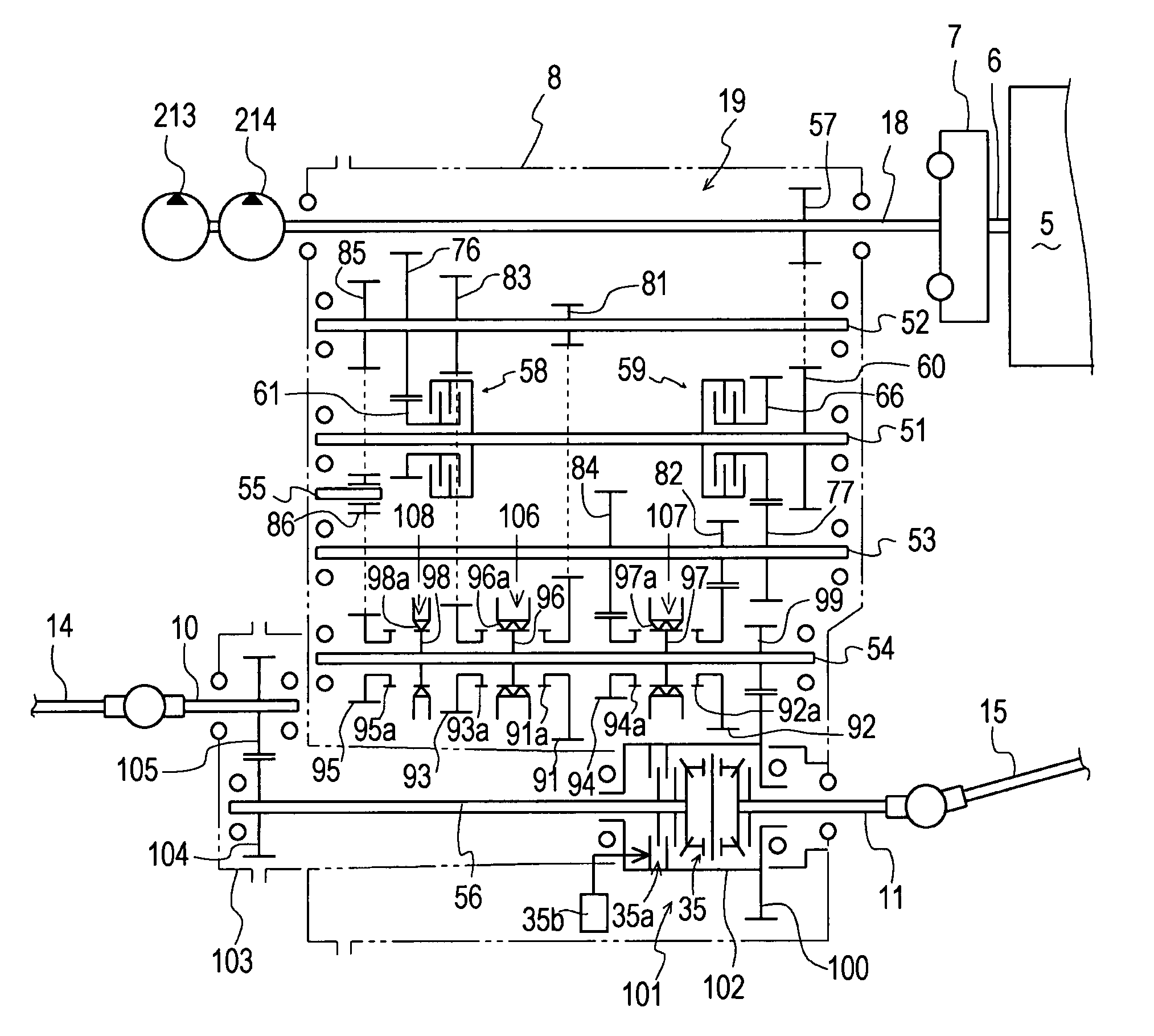
[0242]A multi-speed transmission 199 will be described with reference to FIGS. 30 to 36. Transmission 199 includes a plurality of gearshift drive trains consisting of multi-speed (first to third speed) normal (forward traveling) gear trains, a reverse (backward traveling) gear train, a sub drive train, a main clutch 301 for the multi-speed gearshift drive trains and a sub clutch 302 for the sub drive train. Axles 25 and 36 are driven by one selected among the multi-speed drive trains by engaging main clutch 301. When a gearshift operation is performed, main clutch 301 is disengaged and simultaneously sub clutch 302 is engaged so as to select one of the multi-speed drive trains, thereby transmitting power of engine 5 to axles 25 and 36 through the sub drive train activated by engaging sub clutch 302.

[0243]As shown in FIG. 30, transmission 199 is characteristic in having a sub clutch 302 and the sub drive train for transmitting an auxiliary driving force to a traveling gearshift driv...


PUM


Abstract

A vehicle has an engine, an accelerator for controlling the rotary speed of the engine, an axle and a multi-speed transmission for transmitting power from the engine to the axle. The multi-speed transmission includes an odd-numbered speed drive train for an odd-numbered speed level, a first clutch for the odd-numbered speed drive train, an even-numbered speed drive train for an even-numbered speed level, and a second clutch for the even-numbered speed drive train. In correspondence to operation of the accelerator and an actual speed of the axle, either the odd-numbered speed drive train or the even-numbered speed drive train is selected so as to transmit power from the engine to the axle. A shift-up or shift-down timing between the odd-numbered speed level and the even-numbered speed level relative to variation of the actual speed of the axle is changed according to detection of a tilt angle of the vehicle or a weight of the vehicle.

Description

BACKGROUND OF THE INVENTION[0001]1. Field of the Invention[0002]The invention relates to a vehicle such as a utility vehicle equipped with a cargo, and especially relates to a power transmission system of the vehicle.[0003]2. Related Art[0004]Conventionally, as disclosed in Japanese Laid Open Gazette No. 2000-38042, there is a well-known utility vehicle equipped with a cargo, under which an engine and an axle are disposed and drivingly connected to each other through a power transmission system consisting of a belt-type continuously variable transmission (hereinafter, “CVT”) and a gear-type sub transmission. Due to the CVT, the power transmission system is advantageous for speed change while continuously (not intermittently) transmitting power from the engine to the axle.[0005]However, the CVT has peculiar disadvantages, such as slipping of the belt when wet, short durability of the belt, and inability of engine braking. Further, the gear-type sub transmission requires an onerous cl...

Claims


Application Information

Patent Timeline
Patent Type & Authority Patents(United States)
IPC IPC(8): B60W10/02F16H3/08F16H57/04
CPCF16H3/006F16H3/093F16H61/08F16H61/688F16H57/0409F16H57/0447F16H57/045F16H57/0494Y10T477/78F16H59/66Y10T74/19233Y10T74/19991F16H59/52
Inventor HASEGAWA, TOSHIYUKIEBIHARA, TOMOYUKIKANENOBU, HIDEKIKOGA, KAZUNARI
Owner KANZAKI KOKYUKOKI MFG
Why Eureka
Try Eureka