Moving-object prediction device, virtual-mobile-object prediction device, program, mobile-object prediction method, and virtual-mobile-object prediction method

A technology for predicting devices and moving objects, applied to program modules and moving object prediction methods, can solve the problems of being unable to predict the future position of moving objects with high precision, unable to predict the future position of moving objects, and having no physical meaning

Inactive Publication Date: 2013-06-12
TOYOTA JIDOSHA KK
View PDF7 Cites 44 Cited by
  • Summary
  • Abstract
  • Description
  • Claims
  • Application Information

AI Technical Summary

Problems solved by technology

[0005] However, in the technique described in Japanese Patent Application Laid-Open No. 2007-233646 mentioned above, there is no clear restriction on the area where the moving object can move, and the moving object can move at any position, so it is impossible to predict the moving object with high accuracy. the future position of the
[0006] In addition, in the technology described in the aforementioned Japanese Patent Application Laid-Open No. 2008-238831, risk assessment is not performed as long as the driver has no tendency to perform an operation to change the driving behavior, so there is a possibility that the future position of the moving object cannot be predicted. the problem of the situation
[0007] In addition, in the technique described in the above-mentioned Japanese Patent Laid-Open No. 2005-173703, a database indicating risks under various traffic conditions at intersections and junctions is required, and it may not be able to cope with all situations that actually occur. The problem
Moreover, since the risk assessment is based on the designer's scoring, it does not have physical meaning

Method used


Image

  • Moving-object prediction device, virtual-mobile-object prediction device, program, mobile-object prediction method, and virtual-mobile-object prediction method
  • Moving-object prediction device, virtual-mobile-object prediction device, program, mobile-object prediction method, and virtual-mobile-object prediction method
  • Moving-object prediction device, virtual-mobile-object prediction device, program, mobile-object prediction method, and virtual-mobile-object prediction method

Examples


Embodiment Construction

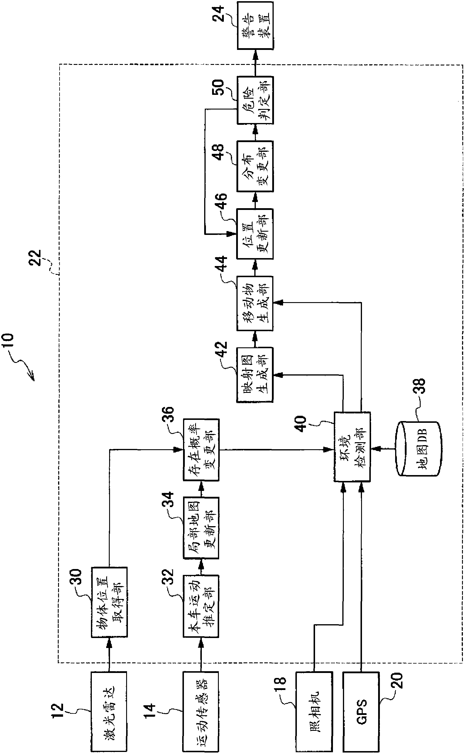
[0072] Hereinafter, embodiments of the present invention will be described in detail with reference to the drawings. In addition, in this embodiment, a case where the present invention is applied to a collision risk determination device mounted on a vehicle will be described as an example.

[0073] like figure 1 As shown, the collision risk determination device 10 according to the first embodiment includes: the laser radar 12 scans one-dimensionally (horizontally) while irradiating laser light toward the front of the own vehicle as the determination target range, and detects the laser light by reflection of the laser light. The two-dimensional position of the irradiated object; the motion sensor 14, the motion sensor 14 detects the motion state of the vehicle; the camera 18, the camera 18 photographs the front of the vehicle; the position of the host vehicle; and a computer 22 that generates local map information recording the presence of a stationary object ahead as seen fro...


PUM


Abstract

An environment detection unit (40) detects the positions, motion states, and movement states of moving objects, and also detects multiple types of road-division regions and stationary-object regions. A mapping generation unit (42) generates an existence-possibility mapping in which existence possibilities are assigned to the detected road-division regions and stationary-object regions. On the basis of the detected positions, motion states, and movement states of the abovementioned moving objects, a moving-object generation unit (44) generates a moving-object position distribution and movement-state distribution and records said distributions in the existence-possibility mapping. On the basis of said moving-object movement-state distribution, a position update unit (46) moves the moving-object position distribution. A distribution change unit (48) changes the moved position distribution on the basis of the existence possibilities in the existence-possibility mapping, and a future position distribution for the moving objects in the existence-possibility mapping is predicted. This makes it possible to predict future positions of moving objects in a variety of situations with high precision.

Description

technical field [0001] The present invention relates to a moving object prediction device, a virtual moving object prediction device, a program module, a moving object prediction method, and a virtual moving object prediction method, and particularly relates to a moving object prediction device, a program module, and a moving object prediction device for predicting the future position of a moving object A method, a virtual living animal prediction device, a program module, and a virtual living animal prediction method for predicting the future position of a virtual living animal. Background technique [0002] Conventionally, there is known an object travel path prediction device that generates a temporal-spatial trajectory of the change in the position of the object over time and performs probabilistic prediction of the object travel path (Japanese Patent Application Laid-Open 2007- 233646). In this object travel path prediction device, a trajectory capable of ensuring safe...

Claims


Application Information

Patent Timeline
Patent Type & Authority Applications(China)
IPC IPC(8): G08G1/16B60R21/00
CPCG08G1/166G06T2207/20076G06T2207/30261G06T7/246G06V20/58G06V40/10
Inventor 清水司大滨吉纮永田真一清水政行佐久川纯
Owner TOYOTA JIDOSHA KK
Why Eureka
Try Eureka