

Roller type pressure cleaning device
A cleaning device and pressure technology, applied in cleaning methods and utensils, cleaning methods using liquids, chemical instruments and methods, etc., can solve the problems of low cleaning efficiency, increase the labor intensity of cleaning workers, and unclean cleaning, and improve cleaning. Cleanliness, realize cleaning automation, reduce labor intensity
- Summary
- Abstract
- Description
- Claims
- Application Information
AI Technical Summary
Problems solved by technology
Method used
Image

Examples
Embodiment Construction
[0043] The technical solution of the present invention will be further described below in conjunction with the accompanying drawings and through specific embodiments
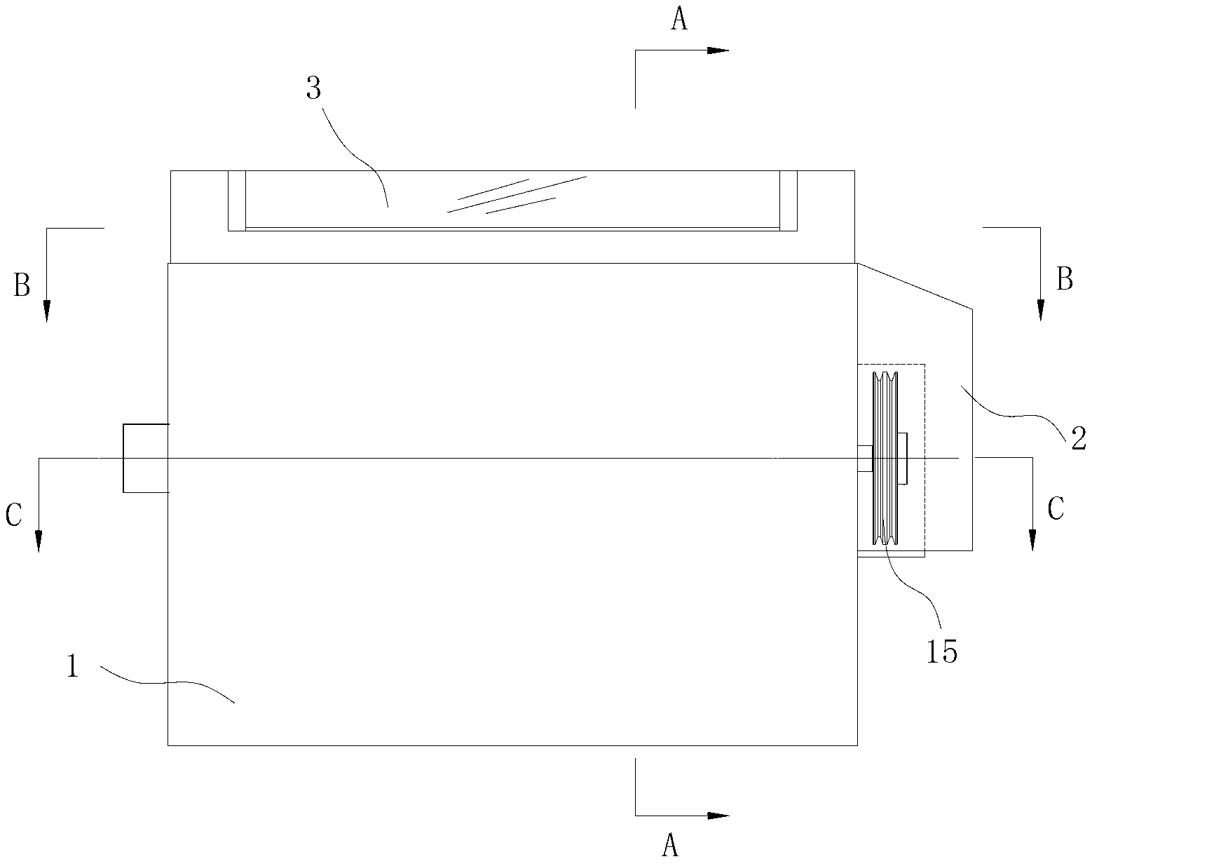
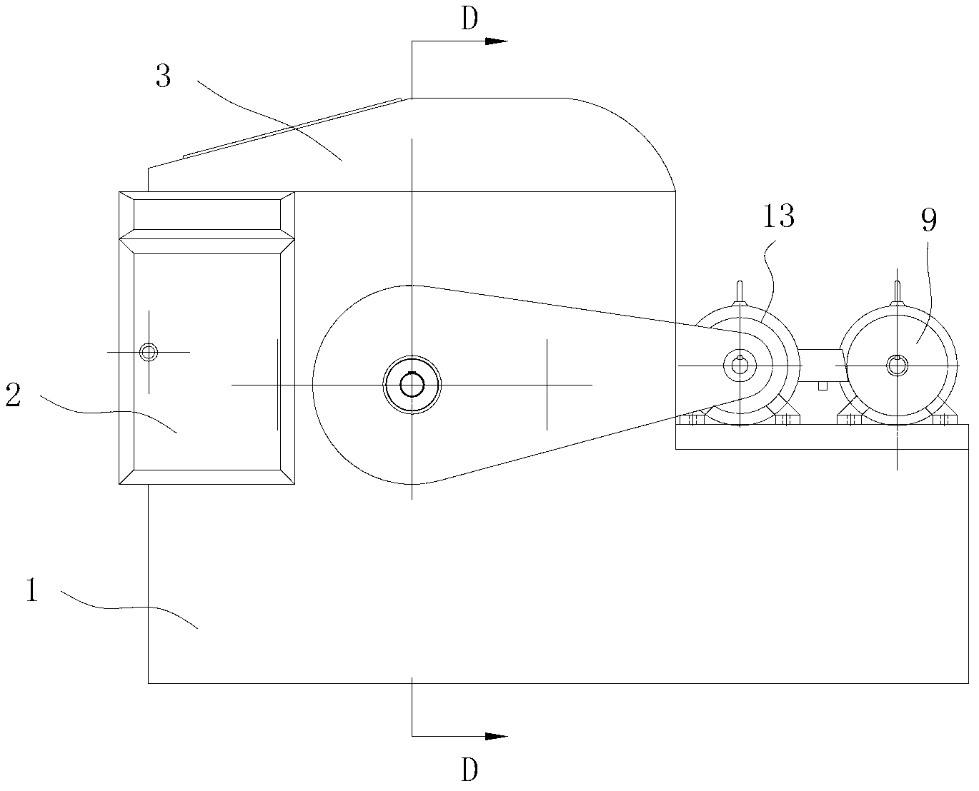
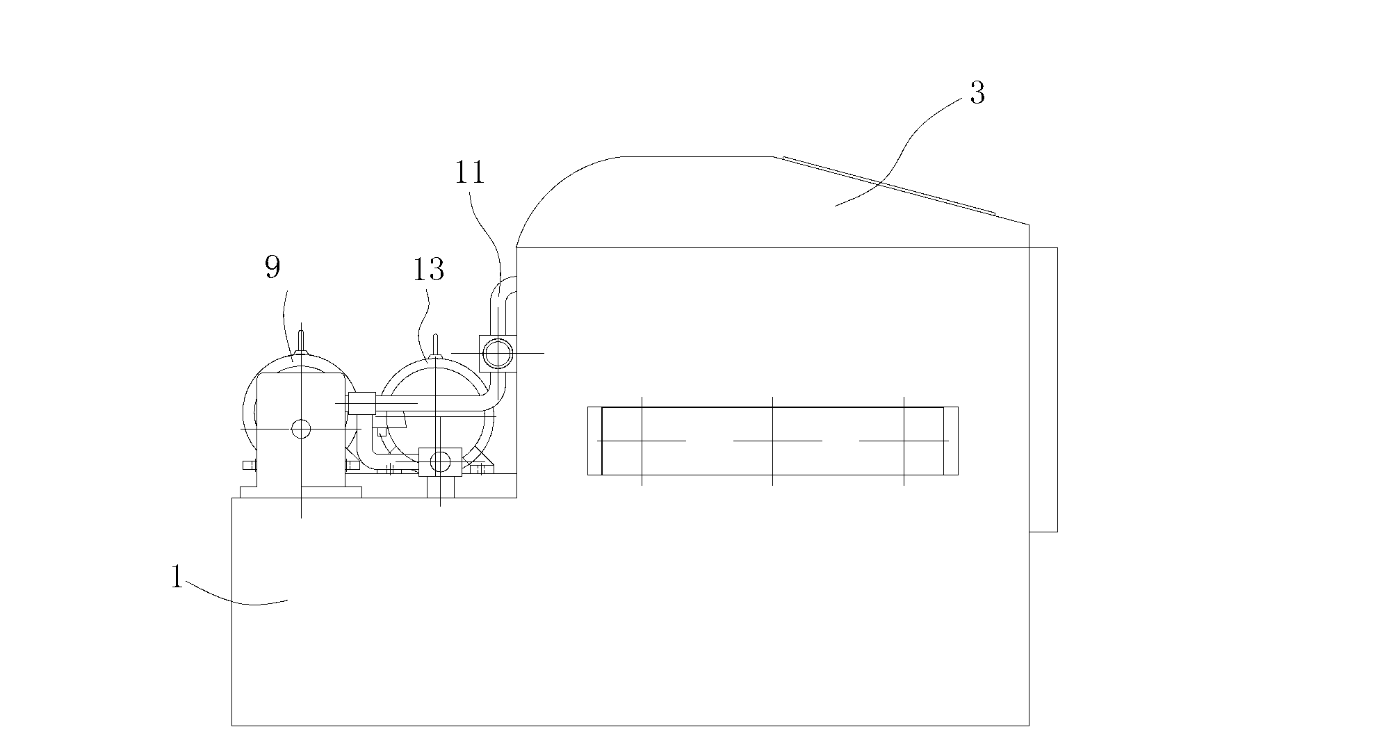
[0044] Such as Figure 1-8 As shown, the roller type pressure cleaning device shown in this embodiment includes a body 1, which has a cavity for accommodating the workpiece 23 to be cleaned, and an openable cover 3 is arranged on the top of the body 1, and the body is also provided with A support assembly for supporting the workpiece 23 to be cleaned and keeping the workpiece 23 to be cleaned in a rotating state, a cleaning assembly for cleaning the workpiece 23 and a controller 2 for controlling the actions of the support assembly and the cleaning assembly.
[0045] The support assembly includes a driving shaft 4 arranged inside the body 1, two driven shafts 5 are arranged in parallel with the driving shaft 4 inside the body 1, and the two driven shafts 5 are respectively arranged on both sides of the driving s...
PUM
 Abstract
Description
Claims
Application Information