Disc unloading mechanism of dual take-up machine

A wire take-up machine and frame technology, applied in the field of cable equipment, can solve problems such as unsmooth reel unloading, stuck wire reel production efficiency, thrust deviation from the center of gravity of the wire reel, etc., so as to achieve fast unloading and avoid wire reel The effect of jamming and unloading force is small

CN103157698AInactive Publication Date: 2013-06-19THE NORTHWEST MACHINE
0 Cites 1 Cited by

Patent Information

Authority / Receiving Office
CN · China
Patent Type
Applications(China)
Current Assignee / Owner
Publication Date
2013-06-19
Estimated Expiration
Not applicable · inactive patent

Smart Images

  • Figure 1
    Figure 1
  • Figure 2
    Figure 2
  • Figure 3
    Figure 3
Patent Text Reader

Abstract

The invention discloses a disc unloading mechanism of a dual take-up machine. The disc unloading mechanism comprises a first disc unloading mechanism and a second disc unloading mechanism which are arranged on the front side and the rear side and adopt the same structure, each disc unloading mechanism comprises an end cover, a pressure spring, a shaft, a machine frame, a hollow shaft, a big rotary disc, a push plate, a bracket, a membrane cylinder, a hinge chain, a lever and a pressing wheel, wherein the hollow shaft is mounted on the machine frame; the big rotary disc is mounted at the right end of the hollow shaft; the shaft is arranged in the hollow shaft; the push plate is arranged on the right side of the hollow shaft and fixedly connected with the shaft; the left end of the shaft is located out of the hollow shaft; the end cover is mounted at the left end part of the shaft; the pressure spring is arranged between the end cover and the hollow shaft; the membrane cylinder is fixedly mounted at the lower part of the machine frame through the bracket; the membrane cylinder is located below the hollow shaft; the hinge chain is fixedly connected onto a piston rod of the membrane cylinder; one end of the lever is connected with the hinge chain; the other end of the lever is connected with the pressing wheel; and the middle part of the lever is connected with the bracket and can rotate around the bracket. The disc unloading mechanism of the dual take-up machine has a compact structure, is convenient and quick to use, is smooth for unloading the disc, and has high in production efficiency.
Need to check novelty before this filing date? Find Prior Art

Description

Technical field

[0001] The invention belongs to the technical field of cable equipment, and specifically relates to a double-reel take-up machine for winding copper wire, aluminum wire, copper alloy wire and aluminum alloy wire, and in particular to a double-reel take-up machine. Disk agency. Background technique

[0002] The reel unloading mechanism of the existing double-reel take-up machine adopts a cylinder to push the end surface of the take-up reel to discharge the reel. The disc unloading mechanism of this structure has the following shortcomings in use: 1. The cylinder push rod must pass through the large turntable. Therefore, the large turntable must be machined with a long round hole so that the cylinder push rod touches the end surface of the take-up disc when unloading the disc; 2. The stop position of the oblong hole on the large turntable must be detected when the machine is stopped to ensure that the oblong hole is aligned with the cylinder push rod, otherwise the...

Examples

Embodiment Construction

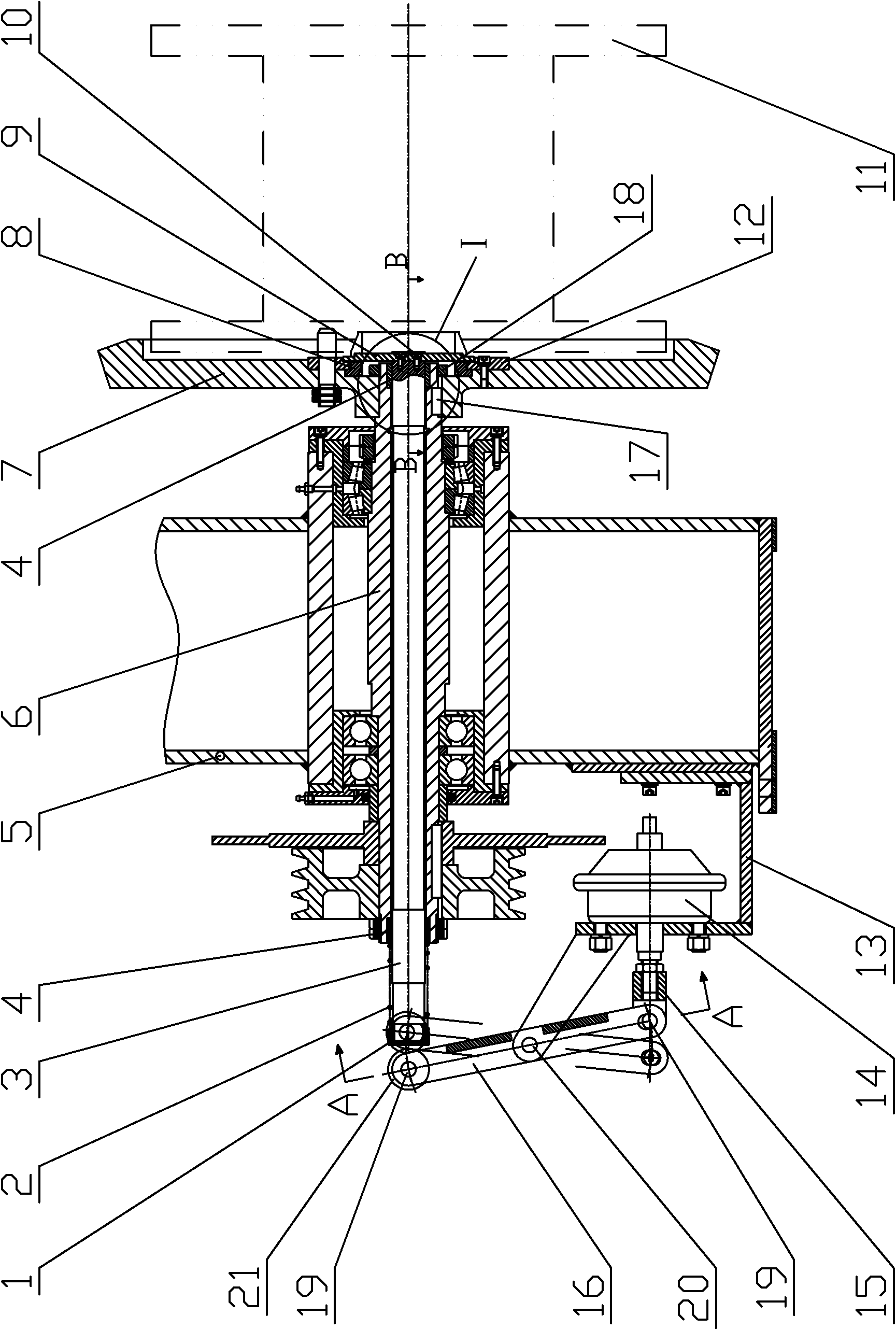
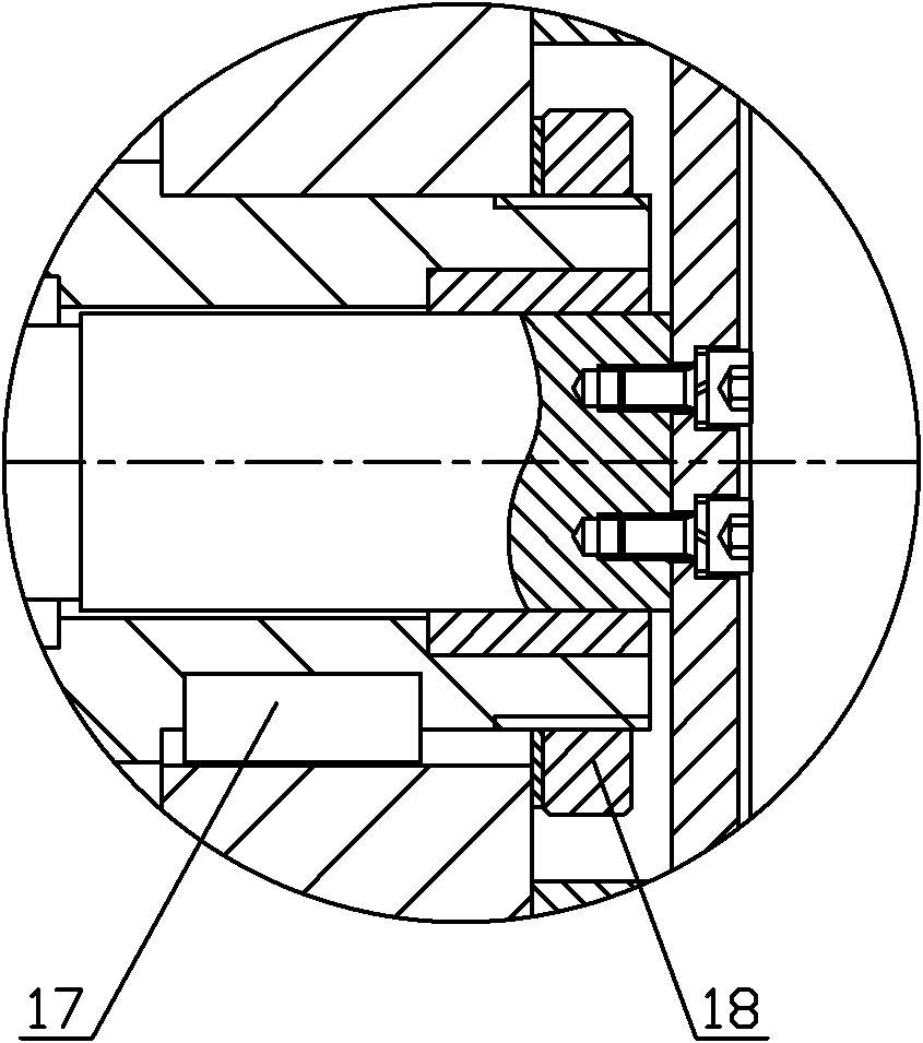
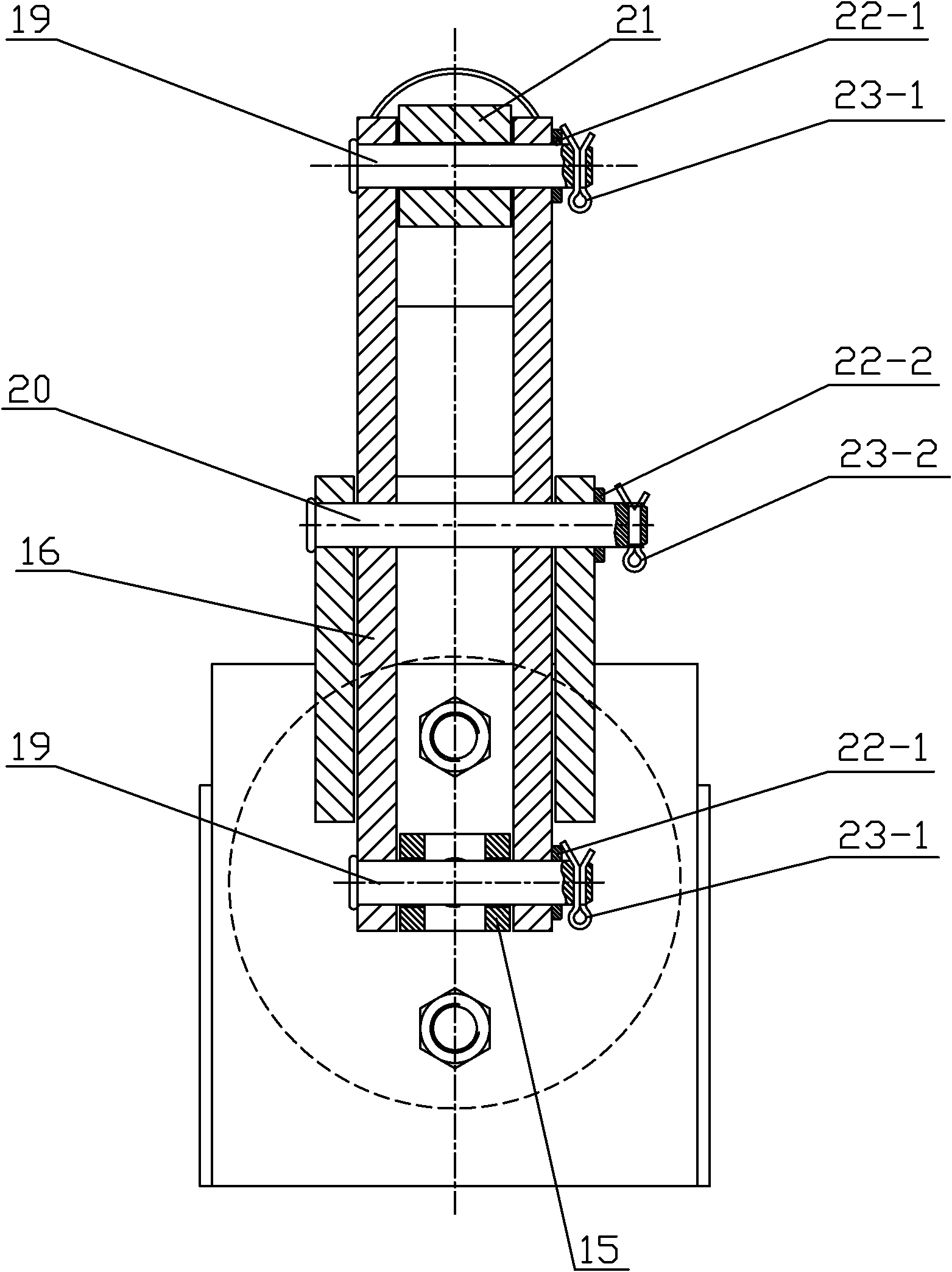
[0033] Such as Figure 1 to Figure 4 As shown, the present invention is composed of a first unloading mechanism and a second unloading mechanism arranged in parallel in the front and rear. The first and second unloading mechanisms have the same structure and both include an end cover 1, a compression spring 2, and a shaft. 3. Frame 5, hollow shaft 6, large turntable 7, push plate 9, bracket 13, film cylinder 14, hinge 15, lever 16 and pressure wheel 21, said hollow shaft 6 is installed on frame 5, said large The turntable 7 is installed at the right end of the hollow shaft 6. The shaft 3 is arranged in the hollow shaft 6, and the push plate 9 is arranged on the right of the hollow shaft 6 and is fixedly connected to the shaft 3; the left end of the shaft 3 is located on the hollow shaft 6. In addition, the end cover 1 is installed at the left end of the shaft 3, the compression spring 2 is arranged between the end cover 1 and the hollow shaft 6; the thin film cylinder 14 is fix...