Diversion tunnel vertical shaft lock chamber structure in concealed body

A diversion tunnel and stealth technology, which is applied in water conservancy projects, hydroelectric power stations, hydroelectric power generation, etc., can solve the problem of water blocking by filling materials.

Active Publication Date: 2013-06-19
POWERCHINA CHENGDU ENG
View PDF4 Cites 4 Cited by
  • Summary
  • Abstract
  • Description
  • Claims
  • Application Information

AI Technical Summary

Problems solved by technology

However, after the sluice chamber is moved underground, when the sluice chamber bottom plate wears or the moving mass affects the lower sluice, and water leakage affects the sealing construction of the diversion tunnel, it is impossible to throw filling material to stop the water on the upstream of the sluice chamber.

Method used


Image

  • Diversion tunnel vertical shaft lock chamber structure in concealed body
  • Diversion tunnel vertical shaft lock chamber structure in concealed body
  • Diversion tunnel vertical shaft lock chamber structure in concealed body

Examples


Embodiment Construction

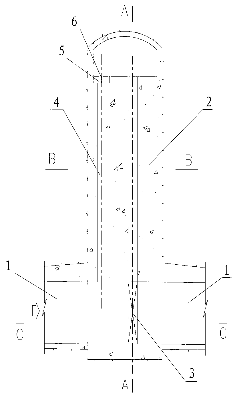
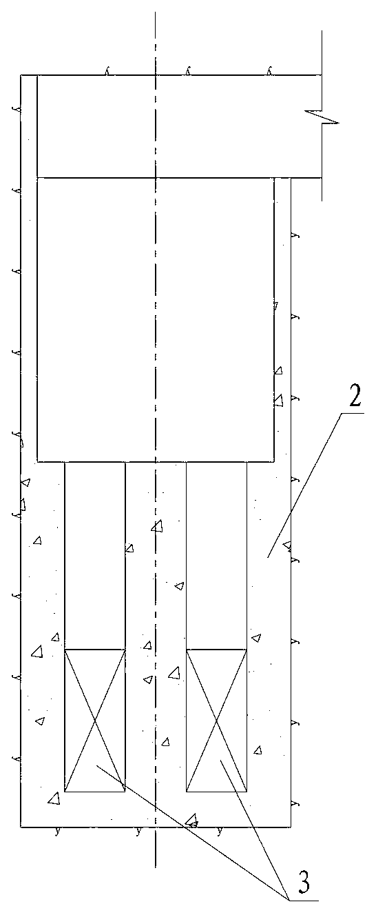
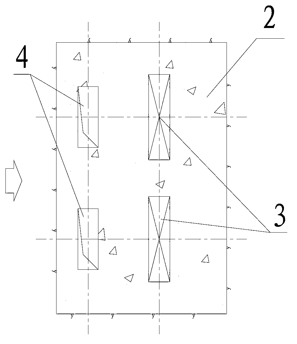
[0016] Such as figure 1 , figure 2 , image 3 as well as Figure 4 Shown is a device provided by the present invention that can be conveniently placed in a concealed body by throwing filling materials into the diversion tunnel when the bottom of the lock chamber is worn or the moving mass is affecting the gate, and water leakage affects the diversion tunnel plugging construction. Diversion tunnel shaft lock chamber structure. The diversion tunnel shaft lock chamber structure includes a diversion tunnel 1 passing through the concealed body and a shaft-type lock chamber body 2 arranged on the diversion tunnel 1 in the concealed body. In the shaft-type lock chamber body 2 The cut-off gate 3 that cuts off the diversion hole 1 is arranged inside, and also includes a parabolic hole 4, and the parabolic hole 4 is arranged on the diversion hole 1 in front of the cut-off gate 3 in the concealed body. When the diversion hole 1 is used, the diversion hole 1 can be blocked by directl...


PUM


Abstract

The invention discloses a diversion tunnel vertical shaft lock chamber structure, particularly discloses the diversion tunnel vertical shaft lock chamber structure in a concealed body, and belongs to the technical field of hydraulic structure design and construction. The diversion tunnel vertical shaft lock chamber structure in the concealed body can enable workers to conveniently throw and fill objects into diversion tunnels to stop water when bottom plates of lock chambers are abraded or bed load influences locking and water leakage influences plugging construction of the diversion tunnels. The diversion tunnel vertical shaft lock chamber structure comprises the diversion tunnels penetrating through the concealed body, and vertical shaft lock chamber bodies arranged on the diversion tunnels in the concealed body. Cut-off gates used for cutting off the diversion tunnels are arranged in the vertical shaft lock chamber bodies. The diversion tunnel vertical shaft lock chamber structure further comprises object throwing holes which are formed in the diversion tunnels in front of the cut-off gates in the concealed body. When the objects need to be thrown to block off the diversion tunnels, materials can be directly cast into the object throwing holes to block off the diversion tunnels.

Description

technical field [0001] The invention relates to a tunnel shaft lock chamber structure, in particular to a diversion tunnel shaft lock chamber structure arranged in a hidden body, and belongs to the technical field of design and construction of hydraulic structures. Background technique [0002] In the current water conservancy and hydropower projects, the diversion tunnel is generally provided with a shore tower lock chamber at the water inlet. In alpine and canyon areas, setting up bank-tower lock chambers will lead to excavation of high slopes. The amount of supporting engineering for excavation of high slopes is large, the project investment is large, and the risks of construction and operation of high slopes are also great. The advantage of setting up the shore tower lock chamber at the water inlet is that when the bottom plate of the lock chamber is worn or the moving mass affects the lower gate, and water leakage affects the sealing construction of the diversion tunne...

Claims


Application Information

Patent Timeline
IPC IPC(8): E02B9/02
CPCY02E10/20
Inventor 雷运华刘国勇何兴勇王小波魏丽琴
Owner POWERCHINA CHENGDU ENG
Why Eureka
Try Eureka