
Layered water stop structure for multi-layer aquifer in hydrogeological test

A hydrogeological and aquifer technology, applied in water saving, wellbore/well components, measurement, etc., can solve problems such as failure of normal use of the device, damage of airbags after long-term use, air leakage of the device, etc., to improve practicability, prevent Water is convenient and simple, and the effect of easy assembly

Pending Publication Date: 2022-07-08
SHANDONG INST OF GEOPHYSICAL & GEOCHEM EXPLORATION
View PDF1 Cites 0 Cited by
  • Summary
  • Abstract
  • Description
  • Claims
  • Application Information

AI Technical Summary

Problems solved by technology

[0005] In order to overcome the shortcoming that the long-term use of the air bag will cause damage when the layered water stop is used, the air of the device will leak out after the air bag is damaged, causing groundwater to pour into the device and cause the device to be unable to use normally. Layered water-stop structure of multi-layered aquifers in hydrogeological tests of groundwater backflow caused by air pocket damage

Method used


Image

  • Layered water stop structure for multi-layer aquifer in hydrogeological test
  • Layered water stop structure for multi-layer aquifer in hydrogeological test
  • Layered water stop structure for multi-layer aquifer in hydrogeological test

Examples


Embodiment 1

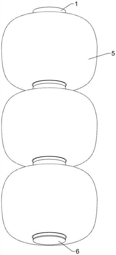
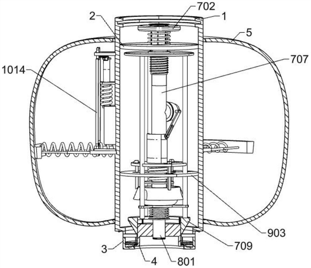
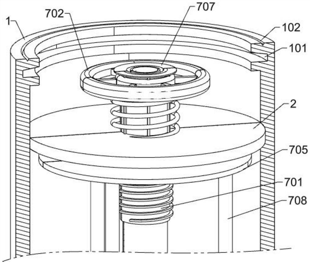
[0031] A multi-layered aquifer layered water-stop structure in a hydrogeological test, such as Figure 1-Figure 11 As shown, there are a plurality of connecting shells 1, the upper part of the inner side of the connecting shell 1 is provided with an annular groove 101, the inner and upper side of the annular groove 101 is provided with an inclined surface, and the upper side of the connecting shell 1 is provided with a prismatic groove 102, the connecting shell A rubber sealing ring is fixed on the lower side of the connecting shell 1, the rubber sealing ring on the lower side of the connecting shell 1 is sealed and matched with the upper prismatic groove 102 of the connecting shell 1 adjacent to the lower side, and a first seal is fixed on the upper part of the inner side of the connecting shell 1. Plate 2, the first sealing plate 2 is located on the lower side of the annular groove 101, the lower side of the connecting shell 1 is fixed with a circular shell 3, the middle of t...

Embodiment 2

[0034] On the basis of Example 1, as Figure 3-Figure 5 As shown, the connecting mechanism includes a rotating sleeve 701, the rotating sleeve 701 is rotatably connected to the middle of the first sealing plate 2, the upper part of the outer side of the rotating sleeve 701 is splined, and the upper part of the outer side of the rotating sleeve 701 is splined connected with a runner 702, The runner 702 is located on the upper side of the first sealing plate 2. The lower side of the runner 702 is fixed with a first annular plate 703. The first annular plate 703 is slidably connected with the rotating sleeve 701. A spring 704, the two ends of the first spring 704 are respectively fixed to the first sealing plate 2 and the first annular plate 703, the lower part of the outer side of the rotating sleeve 701 is threaded, and the lower part of the outer side of the rotating sleeve 701 is threadedly connected with a threaded sleeve 705, a sealing member 706 is provided between the fir...


PUM


Abstract

The invention relates to the technical field of drilling water stopping, in particular to a layered water stopping structure for a multi-layer aquifer in a hydrogeological test. The technical problems that during layered water stopping, an air bag is damaged after being used for a long time, air of the device leaks after the air bag is damaged, underground water flows backwards into the device, and the device cannot be normally used are solved. According to the technical scheme, the layered water stop structure for the multi-layer aquifer in the hydrogeological test comprises a plurality of connecting shells, connecting mechanisms are arranged in the connecting shells and used for connecting every two adjacent connecting shells in a sealed mode, ventilation mechanisms are arranged on the lower portions in the connecting shells, and the ventilation mechanisms are communicated with one another and used for blowing air to an air bag. By arranging the connecting mechanism, the two adjacent connecting shells are tightly extruded, operation is easy, assembling is convenient, and the device is tightly connected through sequential connection; by arranging the ventilation mechanism, the phenomenon that the sliding pipe and the ventilation pipe loosen and leak air in the using process of the device is avoided.

Description

technical field [0001] The invention relates to the technical field of water-stopping of boreholes, in particular to a layered water-stopping structure of a multi-layer aquifer in a hydrogeological test. Background technique [0002] In hydrogeological experiments, in order to collect hydrological data of various underground aquifers, hydrogeological boreholes are often drilled through several aquifers. In order to avoid mixing of water in different aquifers through boreholes, it is often necessary to isolate the holes adjacent aquifers. [0003] In the prior art, for example, the patent with publication number CN114086906A discloses a multi-layered water-stopping structure in a hydrogeological test, which relates to the technical field of drilling water-stopping, and the water-stopping mechanism includes a plurality of splicing mechanisms. and a locking mechanism, the locking mechanism includes a second sleeve, the splicing mechanism includes a first sleeve, the annular ou...

Claims


Application Information

Patent Timeline
IPC IPC(8): E21B33/122E21B47/00E21B41/00
CPCE21B33/122E21B47/00E21B41/00Y02A40/81
Inventor 于嘉宾臧进前魏禅陈大磊陈凡
Owner SHANDONG INST OF GEOPHYSICAL & GEOCHEM EXPLORATION
Learn More