
Vertical water stop structure for hydraulic engineering and construction method

A vertical water stop and water conservancy engineering technology, applied in water conservancy projects, water conservancy engineering equipment, dams, etc., can solve the problems of inability to water level, flow to the other side, difficult effect, etc., to alleviate the water level line, facilitate blocking, and facilitate operation. Effect

Inactive Publication Date: 2021-02-12
王双全
View PDF5 Cites 0 Cited by
  • Summary
  • Abstract
  • Description
  • Claims
  • Application Information

AI Technical Summary

Problems solved by technology

[0002] With the development of the national economy, the basic construction has gradually improved, and the construction of river related projects closely related to people's lives has also been continuously transformed. River reconstruction is the work of comprehensive river management. According to different requirements, the river channel should be controlled, dredged, bank revetment, embankment and other comprehensive treatment. River channel slope protection is an infrastructure in the river channel reconstruction. At present, in some parks, scenic spots and other metropolitan areas Using some vertical concrete structures to retain water can also reduce the loss of soil. However, since the height of the vertical concrete structures is limited, it is difficult to achieve good results only by blocking water and not alleviating the water level. Once the water level exceeds the vertical concrete height, it will overflow directly and flow to the other side, which will cause a certain impact. Therefore, we propose a vertical water-stop structure and construction method for water conservancy projects to solve the above problems

Method used


Image

  • Vertical water stop structure for hydraulic engineering and construction method
  • Vertical water stop structure for hydraulic engineering and construction method
  • Vertical water stop structure for hydraulic engineering and construction method

Examples


Embodiment Construction

[0022] The following will clearly and completely describe the technical solutions in the embodiments of the present invention with reference to the accompanying drawings in the embodiments of the present invention. Obviously, the described embodiments are only some, not all, embodiments of the present invention. Based on the embodiments of the present invention, all other embodiments obtained by persons of ordinary skill in the art without making creative efforts belong to the protection scope of the present invention.

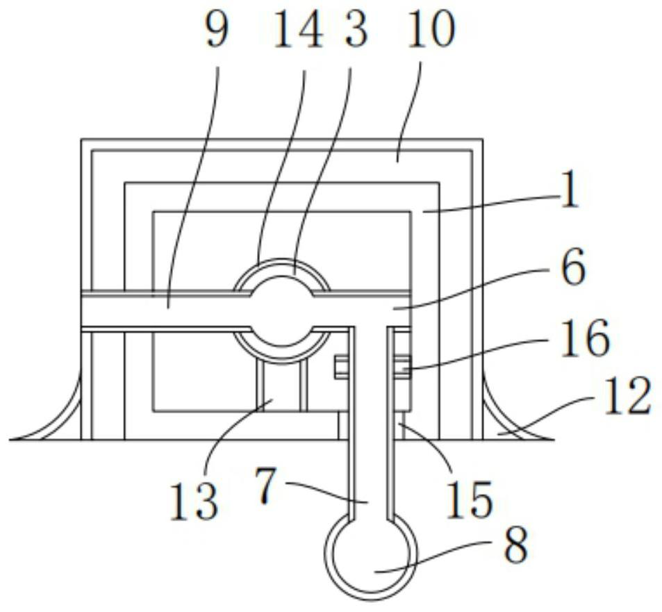
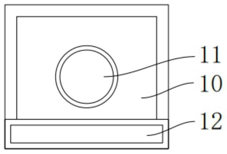
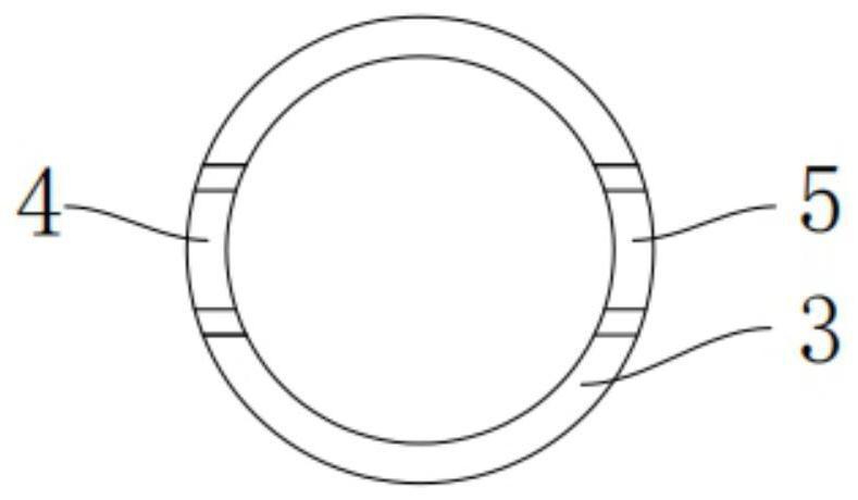
[0023] The present invention provides such Figure 1-4 The vertical water-stop structure of a water conservancy project shown includes a rectangular plate 1, the interior of the rectangular plate 1 is hollow, and round holes 2 are respectively provided on the symmetrical positions of the left and right sides of the rectangular plate 1, and the circular holes 2 is connected to the water pipe 3, the front and rear sides of the water pipe 3 are respectively provi...


PUM


Abstract

The invention discloses a vertical water stop structure for hydraulic engineering and a construction method. The vertical water stop structure for hydraulic engineering comprises a rectangular plate,wherein the inside of the rectangular plate is hollow; round holes are correspondingly formed in the symmetrical positions of the left side surface and the right side surface of the rectangular plate;water pipes are clamped and connected into the round holes; a water inlet is formed in the front side surface of each water pipe, and a water outlet is formed in the rear side surface of each water pipe; a connecting pipe is clamped and connected inside each water outlet; and the bottom surface of each connecting pipe fixedly communicates with one end of a vertical pipe, and the other end of thevertical pipe fixedly communicates with a drainage pipe. The construction method comprises the following steps of Step 1, pipe burying; Step 2, installation and fixation; Step 3, pouring; and Step 4,hole punching. The device can conveniently block water, facilitate water drainage, relieve a water line and guarantee the water stop effect; the water inlet pipe and the connecting pipe are respectively arranged at the front side surface and the rear side surface of the water pipe, so that water drainage can be facilitated; the height of the water line is effectively controlled; and the rectangular plate can be stably arranged on the ground through the arrangement of a concrete base body, and the use is convenient.

Description

technical field [0001] The invention belongs to the technical field of water conservancy engineering, and in particular relates to a vertical water stop structure and a construction method of a water conservancy project. Background technique [0002] With the development of the national economy, the basic construction has gradually improved, and the construction of river related projects closely related to people's lives has also been continuously transformed. River reconstruction is the work of comprehensive river management. According to different requirements, the river channel should be controlled, dredged, bank revetment, embankment and other comprehensive treatment. River channel slope protection is an infrastructure in the river channel reconstruction. At present, in some parks, scenic spots and other metropolitan areas Using some vertical concrete structures to retain water can also reduce the loss of soil. However, since the height of the vertical concrete structure...

Claims


Application Information

Patent Timeline
Patent Type & Authority Applications(China)
IPC IPC(8): E02B1/00E02B3/10
CPCE02B1/00E02B3/10
Inventor 王双全
Owner 王双全
Learn More