A diversion tunnel shaft sluice chamber structure arranged in a hidden body
A technology of diversion tunnel and stealth, which is applied in water conservancy projects, hydropower stations, hydroelectric power generation, etc., and can solve the problems of water stop that cannot be filled by throwing materials
- Summary
- Abstract
- Description
- Claims
- Application Information
AI Technical Summary
Problems solved by technology
Method used
Image
Examples
Embodiment Construction
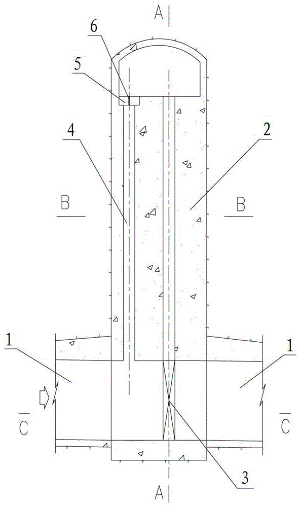
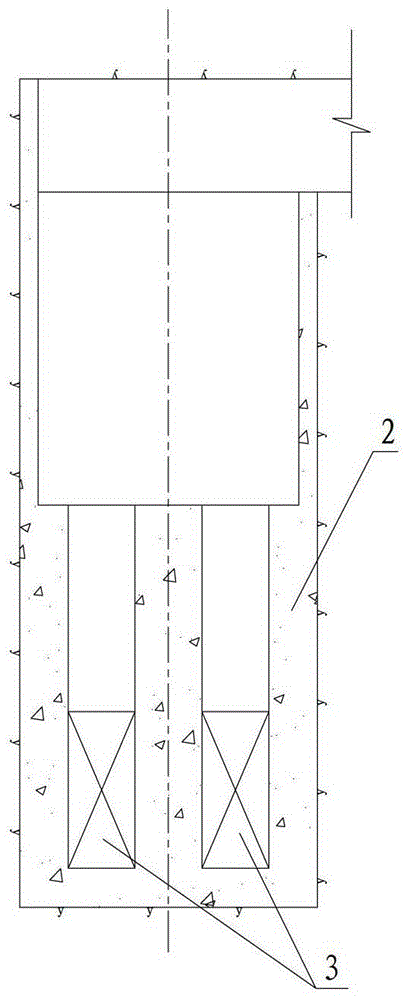
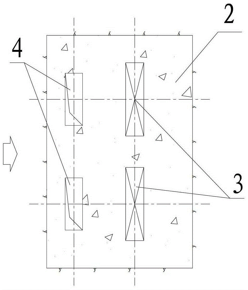
[0016] Such as figure 1 , figure 2 , image 3 as well as Figure 4 Shown is a device provided by the present invention that can be conveniently placed in a concealed body by throwing filling materials into the diversion tunnel when the bottom of the lock chamber is worn or the moving mass is affecting the gate, and water leakage affects the diversion tunnel plugging construction. Diversion tunnel shaft lock chamber structure. The diversion tunnel shaft lock chamber structure includes a diversion tunnel 1 passing through the concealed body and a shaft-type lock chamber body 2 arranged on the diversion tunnel 1 in the concealed body. In the shaft-type lock chamber body 2 The cut-off gate 3 that cuts off the diversion hole 1 is arranged inside, and also includes a parabolic hole 4, and the parabolic hole 4 is arranged on the diversion hole 1 in front of the cut-off gate 3 in the concealed body. When the diversion hole 1 is used, the diversion hole 1 can be blocked by directl...
PUM
 Abstract
Description
Claims
Application Information
 - R&D
- Intellectual Property
- Life Sciences
- Materials
- Tech Scout
- Unparalleled Data Quality
- Higher Quality Content
- 60% Fewer Hallucinations
Browse by: Latest US Patents, China's latest patents, Technical Efficacy Thesaurus, Application Domain, Technology Topic, Popular Technical Reports.
© 2025 PatSnap. All rights reserved.Legal|Privacy policy|Modern Slavery Act Transparency Statement|Sitemap|About US| Contact US: help@patsnap.com


