Lens for ultraviolet light-emitting diode (LED) collimation

A lens and ultraviolet technology, applied in semiconductor lighting technology and application fields, can solve problems such as unsatisfactory collimation effect, and achieve the effects of simple structure, prolonged service life and good collimation effect

Active Publication Date: 2013-06-19
CHONGQING INST OF GREEN & INTELLIGENT TECH CHINESE ACADEMY OF SCI
View PDF7 Cites 13 Cited by
  • Summary
  • Abstract
  • Description
  • Claims
  • Application Information

AI Technical Summary

Problems solved by technology

[0006] In view of this, the present invention provides a lens for ultraviolet LED collimation, which adopts the design of free-form surface reflection and refraction combined collimation, realizes the collimation effect with a collimation degree of 2 degrees, and solves the problem of existing LED collimation lenses. The problem of unsatisfactory collimation effect

Method used


Image

  • Lens for ultraviolet light-emitting diode (LED) collimation
  • Lens for ultraviolet light-emitting diode (LED) collimation
  • Lens for ultraviolet light-emitting diode (LED) collimation

Examples


Embodiment 1

[0033] Embodiment 1 adopts the LED collimating lens of integrated design

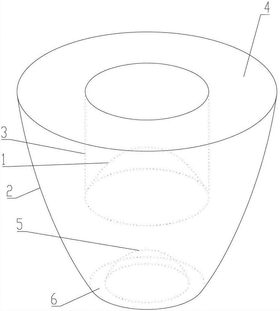
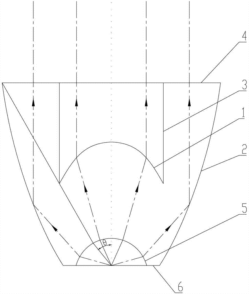
[0034] The lens shown in this embodiment includes a first free-form surface 1 and a total reflection free-form surface 2, the first free-form surface 1 and the total-reflection free-form surface 2 are rotators with the optical axis as the axis, and the total-reflection free-form surface 2 The opening of the opening gradually increases along the exiting direction of the optical axis; the first free-form surface 1 is arranged inside the total reflection free-form surface 2, and the first free-form surface 1 is convex along the exiting direction of the optical axis. The first free-form surface 1 is used to refract the light near the optical axis, so that the light can be emitted parallel to the optical axis; the total reflection free-form surface 2 is used to reflect the light far away from the optical axis, so that the light can emitted parallel to the optical axis.

[0035]The lens in this embodiment al...

Embodiment 2

[0044] Embodiment 2 LED collimating lens with split design

[0045] The lens described in the second embodiment is designed and manufactured separately from optical quartz material and reflective material. like Figure 5 As shown, wherein, the reflective material is used to make the total reflection free-form surface 2; the optical quartz material is used to make the first free-form surface 1 and the second free-form surface 5. In the split design, the lens omits the connecting surface and the outgoing surface, so that the structure of the lens is much simpler than that of the first embodiment, and its manufacture is not as complicated as the lens in the first embodiment. In addition, as an alternative to the second embodiment, the lens portion with the first free-form surface 1 and the second free-form surface 5 and the LED light source 7 in the second embodiment may also be packaged integrally.

[0046] As a further improvement of Embodiments 1 and 2, the first free-form s...


PUM


Abstract

The invention discloses a lens for ultraviolet light-emitting diode (LED) collimation. The lens for the ultraviolet LED collimation comprises a first free-form surface and a total-reflection free-form surface, wherein the first free-form surface and the total-reflection free-form surface are rotary bodies and an optical axis serves as the axle center of the rotary bodies, an opening of the total-reflection free-form surface gradually increases along the emitting direction of the optical axis, the first free-form surface is arranged in the interior of the total-reflection free-form surface, the first free-form surface protrudes along the direction of the optical axis, the first free-form surface is used for carrying out refraction on light which is close to an optical axis area and enabling the light to be capable of emitting parallel to the optical axis, and the total-reflection free-form surface is used for carrying out reflection on light which is away from the optical axis area and enabling the light to be capable of emitting parallel to the optical axis. The lens for the ultraviolet LED collimation is high in collimation degree, long in service life, very suitable for the ultraviolet LED collimation and capable of solving the problems that an original LED collimation lens is complex in structure, low in the collimation degree, not suitable for the ultraviolet LED collimation and the like.

Description

technical field [0001] The invention relates to the field of semiconductor lighting technology and application technology, in particular to a collimating lens capable of collimating light emitted by an LED light source and making the collimating angle less than 2 degrees. Background technique [0002] In recent years, with the development of semiconductor chips and packaging technology, the light efficiency and life of ultraviolet LEDs have been continuously improved, becoming a new generation of ultraviolet light sources. Traditional ultraviolet mercury lamps have high temperature during use, huge power consumption, and short service life. They are likely to cause large environmental pollution during production and processing. Although the industry has been committed to improving them, due to the original hardware Limitations have always been difficult to break through. Ultraviolet LEDs are widely used in various fields because of their advantages such as constant light in...

Claims


Application Information

Patent Timeline
Patent Type & Authority Applications(China)
IPC IPC(8): F21V5/04F21Y101/02F21Y115/10
Inventor 孙秀辉尹韶云杜春雷史浩飞
Owner CHONGQING INST OF GREEN & INTELLIGENT TECH CHINESE ACADEMY OF SCI
Why Eureka
Try Eureka