
Under-screen fingerprint recognition device, electronic equipment

A technology of fingerprint recognition and photoelectric detection, which is applied in character and pattern recognition, computing, computer components, etc. It can solve the problems of poor battery life, large size, compressed battery space, etc., and achieve thinner and lighter fingerprint recognition functions and improved clarity. The effect of lightness and thickness

Active Publication Date: 2022-05-20
GUANGDONG OPPO MOBILE TELECOMM CORP LTD
View PDF26 Cites 0 Cited by
  • Summary
  • Abstract
  • Description
  • Claims
  • Application Information

AI Technical Summary

Problems solved by technology

[0003] However, since the optical lens 730 in the current under-screen optical fingerprint module needs to maintain a certain object distance and image distance from the bottom of the terminal screen and the top of the image sensor 720, respectively, in order to meet the requirements of optical imaging, this is As a result, the bottom of the under-screen optical fingerprint module 10 and the bottom of the display screen 20 need to maintain a relatively large distance L (about 3-6 mm), so that the Z direction of the existing under-screen optical fingerprint solution (refer to Figure 15 , the Z direction (that is, the direction perpendicular to the outward direction of the terminal screen) is large in size, which in turn compresses the battery space of the terminal, resulting in reduced battery capacity and poor battery life.
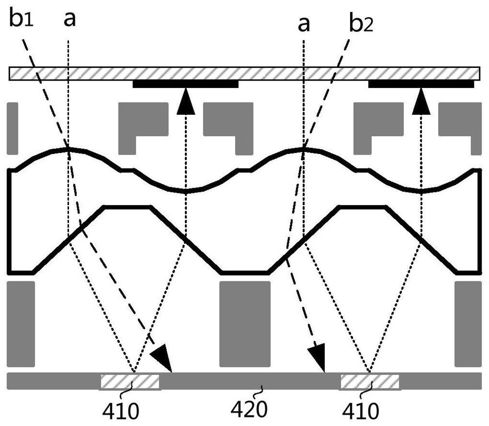
Also, refer to Figure 16 , the under-display optical fingerprint solution with the existing structural design still has obvious crosstalk problems in adjacent pixel units 740

Method used


Image

  • Under-screen fingerprint recognition device, electronic equipment
  • Under-screen fingerprint recognition device, electronic equipment
  • Under-screen fingerprint recognition device, electronic equipment

Examples


Embodiment Construction

[0064] The embodiments of the present application are described in detail below, and those skilled in the art will understand that the following embodiments are intended to explain the present application, and should not be regarded as limiting the present application. Unless otherwise specified, in the following examples that do not explicitly describe specific techniques or conditions, those skilled in the art can carry out according to commonly used techniques or conditions in this field or according to product instructions.

[0065] In one aspect of the embodiments of the present application, an under-display fingerprint recognition device is provided.

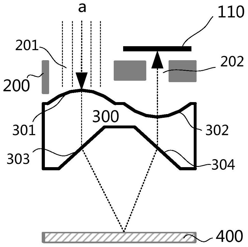
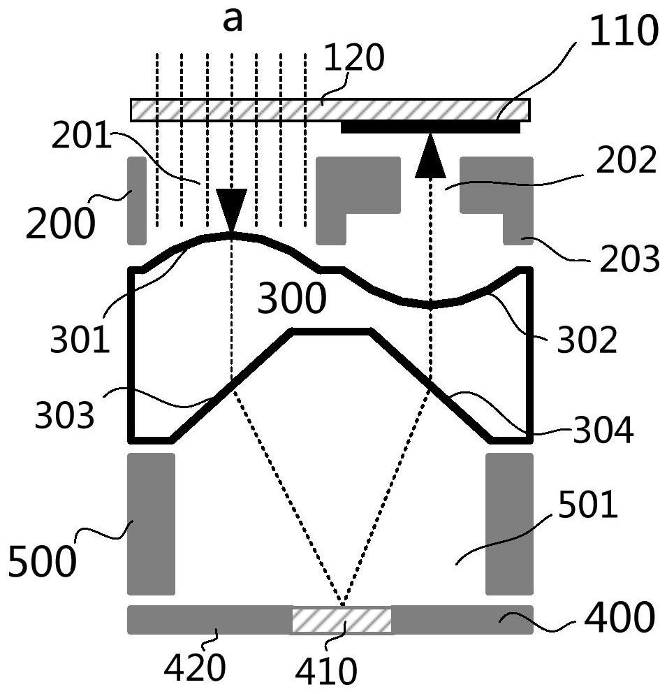
[0066] According to the embodiment of the application, refer to Figure 4 , the fingerprint identification device under the screen is composed of a plurality of optical path units A arranged in an array, refer to figure 1, each optical path unit includes a photodetection unit 110, a first photoresist layer 200, a light g...


PUM

PropertyMeasurementUnit
thicknessaaaaaaaaaa

Abstract

The application proposes an under-screen fingerprint identification device and electronic equipment. The fingerprint recognition device under the screen is composed of a plurality of optical path units arranged in an array, and each optical path unit includes: a first photoresist layer with a first opening and a second opening; a light guide plate arranged on the first photoresist layer One side of the first photoresist layer is provided with a convex area and a concave area, and also has a first refraction surface and a second refraction surface, and the first refraction surface is arranged on a side of the convex area away from the first photoresist layer side, the second refraction surface is arranged on the side of the concave area away from the first photoresist layer, the convex area and the first refraction surface are respectively facing the first opening, and the concave area and the second refraction surface are respectively facing the second opening Yes; the photoelectric detection unit is arranged on the side of the second opening away from the concave area; the reflective layer is arranged on the side of the light guide plate away from the photoelectric detection unit. In this way, the optical path is folded and shaped through the reflective layer to make the fingerprint recognition device under the screen thinner. At the same time, light convergence can achieve the collimation effect of the optical path, reduce crosstalk between optical path units, and improve the clarity of fingerprint imaging.

Description

technical field [0001] The present application relates to the technical field of fingerprint recognition, and specifically, the present application relates to an under-screen fingerprint recognition device and electronic equipment. Background technique [0002] For existing under-screen optical fingerprint terminals, refer to Figure 14 , generally consists of a terminal screen and an under-screen fingerprint sensor 10 . Wherein, the terminal screen is composed of a glass cover 30 and a display panel 20 , and the under-display fingerprint sensor 10 is composed of a module frame 710 , an optical lens 730 and an image sensor 720 . In this way, the light c emitted by the display panel 20 reaches the surface of the finger f through the glass cover plate 30. Since the reflectivity of the light at the valleys and ridges of the fingerprint is different, the intensity of the reflected light at the valleys and ridges of the fingerprint is also different. The reflected light a passes ...

Claims


Application Information

Patent Timeline
Patent Type & Authority Patents(China)
IPC IPC(8): G06V40/13G06V10/147
CPCG06V40/1324G06V10/147
Inventor 吴安平吴雨桐
Owner GUANGDONG OPPO MOBILE TELECOMM CORP LTD
Learn More