Vapor recycling water heater

A water heater and heat energy recovery technology, which is applied to fluid heaters, lighting and heating equipment, etc., can solve problems such as heat waste, and achieve the effects of low cost, simple structure and less improvement.

Inactive Publication Date: 2013-06-19
宁波市江北区众合技术开发有限公司
View PDF0 Cites 3 Cited by
  • Summary
  • Abstract
  • Description
  • Claims
  • Application Information

AI Technical Summary

Problems solved by technology

The disadvantage is that the steam directly enters the air, causing waste of heat

Method used


Image

  • Vapor recycling water heater
  • Vapor recycling water heater

Examples


Embodiment Construction

[0011] The following descriptions are only preferred embodiments of the present invention, and therefore do not limit the protection scope of the present invention.

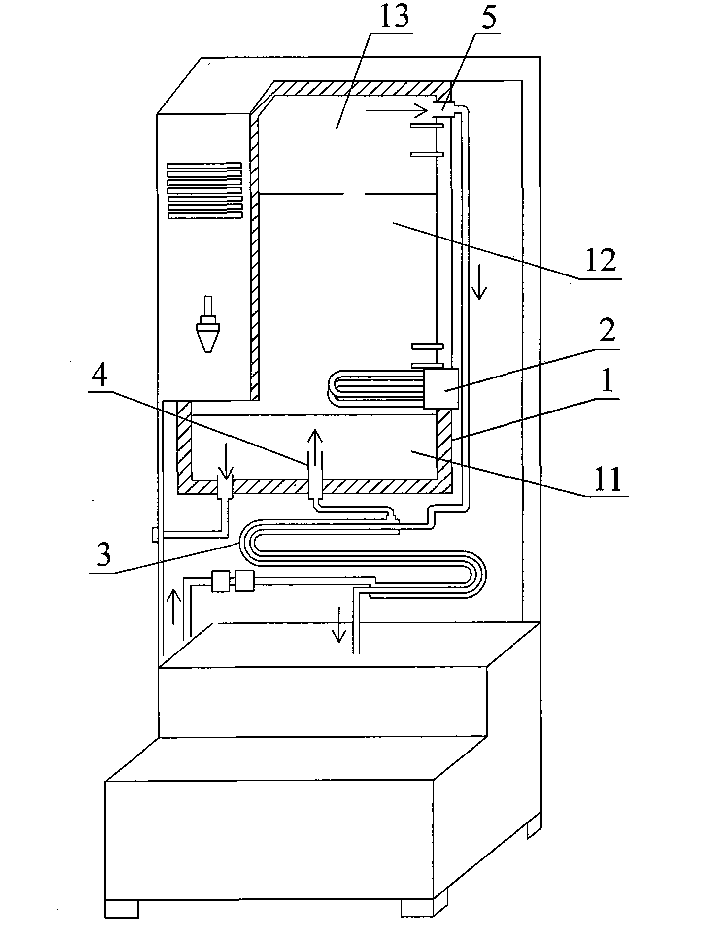
[0012] Examples, see figure 1 Shown: steam recovery water heater, including hot water chamber 1. A heater 2 is provided in the middle of the hot water chamber 1 . The bottom of the wall of the hot water chamber 1 has a water inlet 4, and the top of the wall of the hot water chamber 1 has a steam port 5. In this way, cold water with a relatively low temperature enters the hot water chamber 1 through the water inlet 4, and is heated by the heater 2 to form hot water, and part of the hot water continues to increase in temperature to form hot steam. That is, the inside of the hot water chamber 1 forms a cool water zone 11 with a relatively low temperature, a hot water zone 12 with a temperature of 100° C., and a steam zone 13 mainly composed of steam from bottom to top. Obviously, the hot water outlet of the water...


PUM


Abstract

The invention discloses a vapor recycling water heater. The vapor recycling water heater comprises a hot water cavity. A heater is arranged in the inner portion of the hot water cavity. A water inlet and a vapor opening are arranged in the wall of the hot water cavity. The water inlet is arranged in the bottom of the hot water cavity. The vapor opening is arranged in the upper portion of the hot water cavity. The water heater is arranged in the middle of the hot water cavity. A heat energy recycling device is arranged on the vapor recycling hot water device at the same time. A vapor pipe is arranged on the hot energy recycling device. A cold water pipe is sleeved on the outer portion of a vapor pipe. The vapor pipe is communicated with the vapor opening in a sealing mode. The cold water pipe is communicated with the water inlet in a sealing mode. According to the vapor recycling water heater, the quantity of heat of the vapor can be used repeatedly, thus the vapor recycling water heater is energy-saving.

Description

technical field [0001] The invention relates to the technical field of water heaters, in particular to a steam recovery water heater. Background technique [0002] Generally, a water heater includes a hot water chamber, a heater is arranged inside the hot water chamber, a water inlet for inputting cold water into the hot water chamber is provided on the wall of the hot water chamber, and a water inlet for outputting steam is provided on the wall of the hot water chamber to supply heat. Steam port for depressurizing the water chamber. Of course, the water heater has devices such as a hot water outlet for outputting hot water, necessary control circuits, and the like. In this way, cold water with a lower temperature enters the hot water chamber through the water inlet, becomes hot water after being heated by the heater, and part of the hot water becomes steam, which is discharged through the steam port. Its disadvantage is that steam directly enters the air, causing waste of...

Claims


Application Information

Patent Timeline
Patent Type & Authority Applications(China)
IPC IPC(8): F24H9/00
Inventor 李咏
Owner 宁波市江北区众合技术开发有限公司
Why Eureka
Try Eureka