Method and device for high-dynamic star sensor image intensifier error compensation

A star sensor, image intensifier technology, applied in the field of aerospace measurement, can solve the problems of low compensation efficiency, poor test accuracy, inaccurate solution of internal and external parameters, etc. Effect

Active Publication Date: 2013-06-19
BEIHANG UNIV
View PDF3 Cites 16 Cited by
  • Summary
  • Abstract
  • Description
  • Claims
  • Application Information

AI Technical Summary

Problems solved by technology

However, these methods are not suitable for star sensors because, first of all, the above methods are only for error compensation in X-ray imaging systems, and the error compensation schemes for other frequency optical imaging systems have not been proposed; secondly, the above methods are The external installation error of the instrument, the optical system error and the image intensifier error are coupled together without separation, so that the test accuracy after compensation is still poor. In addition, the coupling of errors will also lead to inaccurate solutions for internal and external parameters; third, the above method Through complex polynomial and interpolation calculations, the grayscale reconstruction of the target point is performed pixel by pixel, and the compensation efficiency is low

Method used


Image

  • Method and device for high-dynamic star sensor image intensifier error compensation
  • Method and device for high-dynamic star sensor image intensifier error compensation
  • Method and device for high-dynamic star sensor image intensifier error compensation

Examples


Embodiment Construction

[0034] The present invention will be further described in detail below in conjunction with the accompanying drawings and specific embodiments.

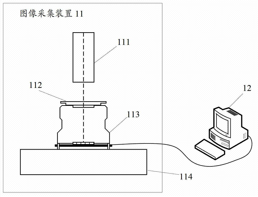
[0035] figure 1 It is a schematic diagram of the composition of the error compensation device of the high dynamic star sensor image intensifier of the present invention, as figure 1 As shown, the error compensation device includes an image acquisition device 11 and a data processing device 12; wherein,

[0036] The image acquisition device 11 is used to collect target imaging images, and send the target imaging images to a data processing device; the image acquisition device 11 specifically includes a light source 111, a target 112, and a high dynamic star sensor 113 without an optical lens and the platform base 114; the target 112 is bonded to the input end face of the high dynamic star sensor 113 that removes the optical lens; the light direction of the light source 111 is parallel to the visual axis of the high dynamic star sensor...


PUM


Abstract

The invention discloses a method for high-dynamic star sensor image intensifier error compensation. The method comprises the following steps: collecting target imaging images through an image collecting device, establishing image intensifier imaging models, establishing the mapping relations of target mass center positions and the errors of the image intensifier according to the imaging models, and conducting error compensation to the mass center positions of a star point according to the mapping relations. The invention further discloses a device for high-dynamic star sensor image intensifier error compensation. By means of the method and the device for high-dynamic star sensor image intensifier error compensation, the errors of the image intensifier can be fast and accurately compensated, the speed of image intensifier error compensation is greatly accelerated, the time of error compensation is shortened, and the testing precision of the high-dynamic star sensor is improved.

Description

technical field [0001] The invention relates to the field of aerospace measurement, in particular to an error compensation method and device for an image intensifier of a high dynamic star sensor. Background technique [0002] The star sensor is an aerospace measurement instrument that observes stars through an imaging system and provides high-precision attitude information for spacecraft. Since its appearance, it mainly provides attitude information for static satellites whose motion angular velocity is less than 0.5 degrees per second. With the development of aerospace technology, a large number of highly dynamic space vehicles with a motion angular velocity greater than 1 degree per second have emerged, and they need to obtain high-precision attitude information under high dynamic conditions in real time. Therefore, the research and development of high dynamic star sensors suitable for this kind of spacecraft has become a new hot spot in star sensor research. [0003] B...

Claims


Application Information

Patent Timeline
Patent Type & Authority Applications(China)
IPC IPC(8): G01C25/00
Inventor 张广军江洁熊琨魏新国闫劲云
Owner BEIHANG UNIV
Why Eureka
Try Eureka