
Plastic optical fiber with W-shaped refractive index distribution

A technology of refractive index distribution and plastic optical fiber, which is applied in the direction of multi-layer core/clad optical fiber, clad optical fiber, optical waveguide light guide, etc., can solve the problems of long monitoring distance, low false alarm rate and high false alarm rate, and achieve The effect of convenient processing and manufacturing and low cost

Inactive Publication Date: 2013-06-19
XIAN JINHE OPTICAL TECH
View PDF0 Cites 0 Cited by
  • Summary
  • Abstract
  • Description
  • Claims
  • Application Information

AI Technical Summary

Problems solved by technology

[0002] The optical fiber perimeter sensing monitoring system is a new security system, which has many advantages such as anti-electromagnetic interference and long monitoring distance. In the current optical fiber perimeter sensing monitoring system, the proportion of optical fiber interference method is relatively large, which has the advantages of It has the characteristics of low false negative rate and high precision, but its poor positioning ability and high false positive rate seriously affect its popularization and application
Compared with optical fiber interference, the optical fiber microbend sensing device has the advantages of low cost, positionability, and low false alarm rate, but it is difficult to combine with the fence or railing in the perimeter, and its practical application is very limited. The main problem is that the existing microbend sensing The device still mainly uses ordinary communication optical fiber. The structure design of ordinary communication optical fiber is to reduce the microbending loss as much as possible. contradictory

Method used


Image

  • Plastic optical fiber with W-shaped refractive index distribution
  • Plastic optical fiber with W-shaped refractive index distribution

Examples


Embodiment Construction

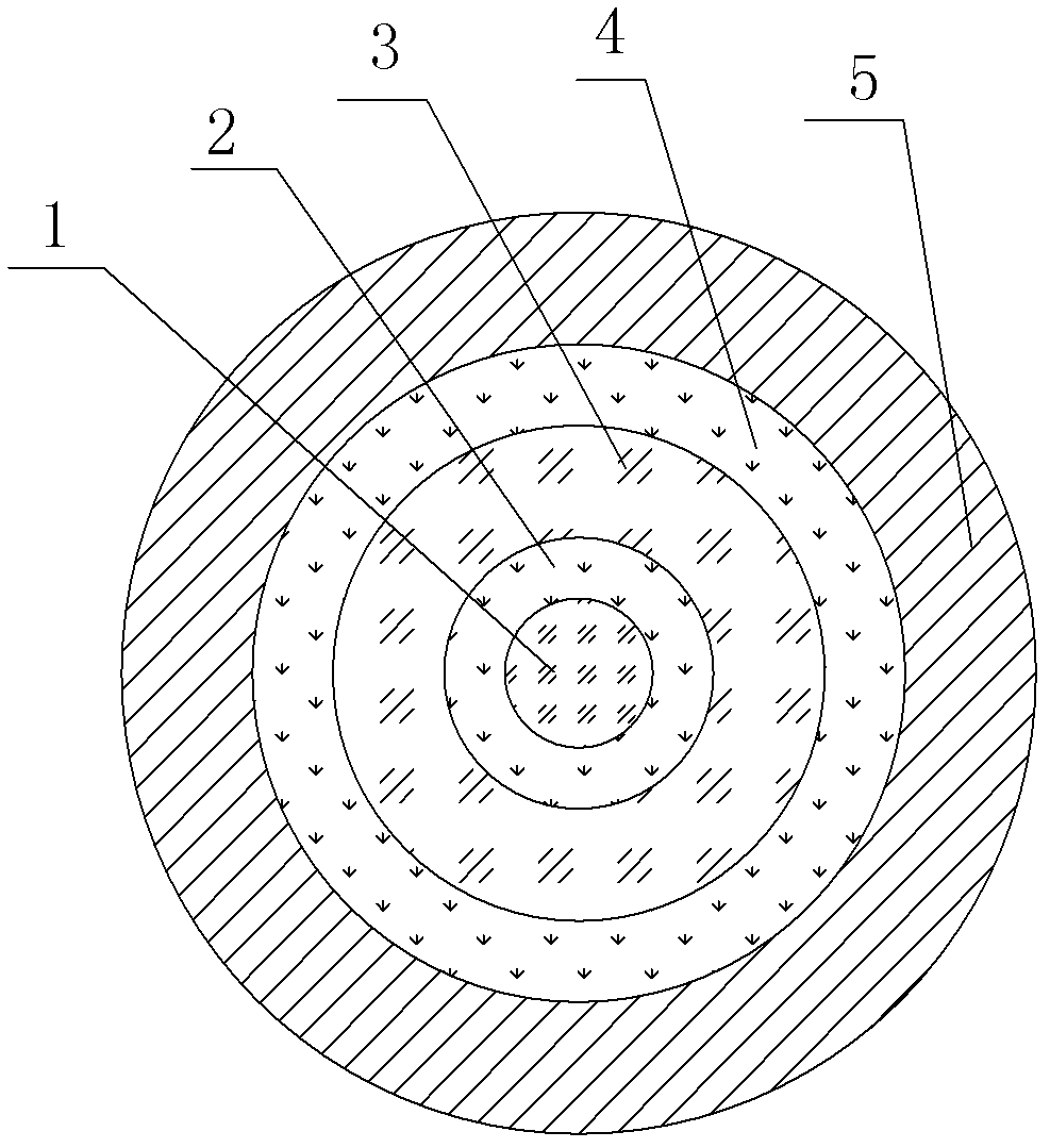
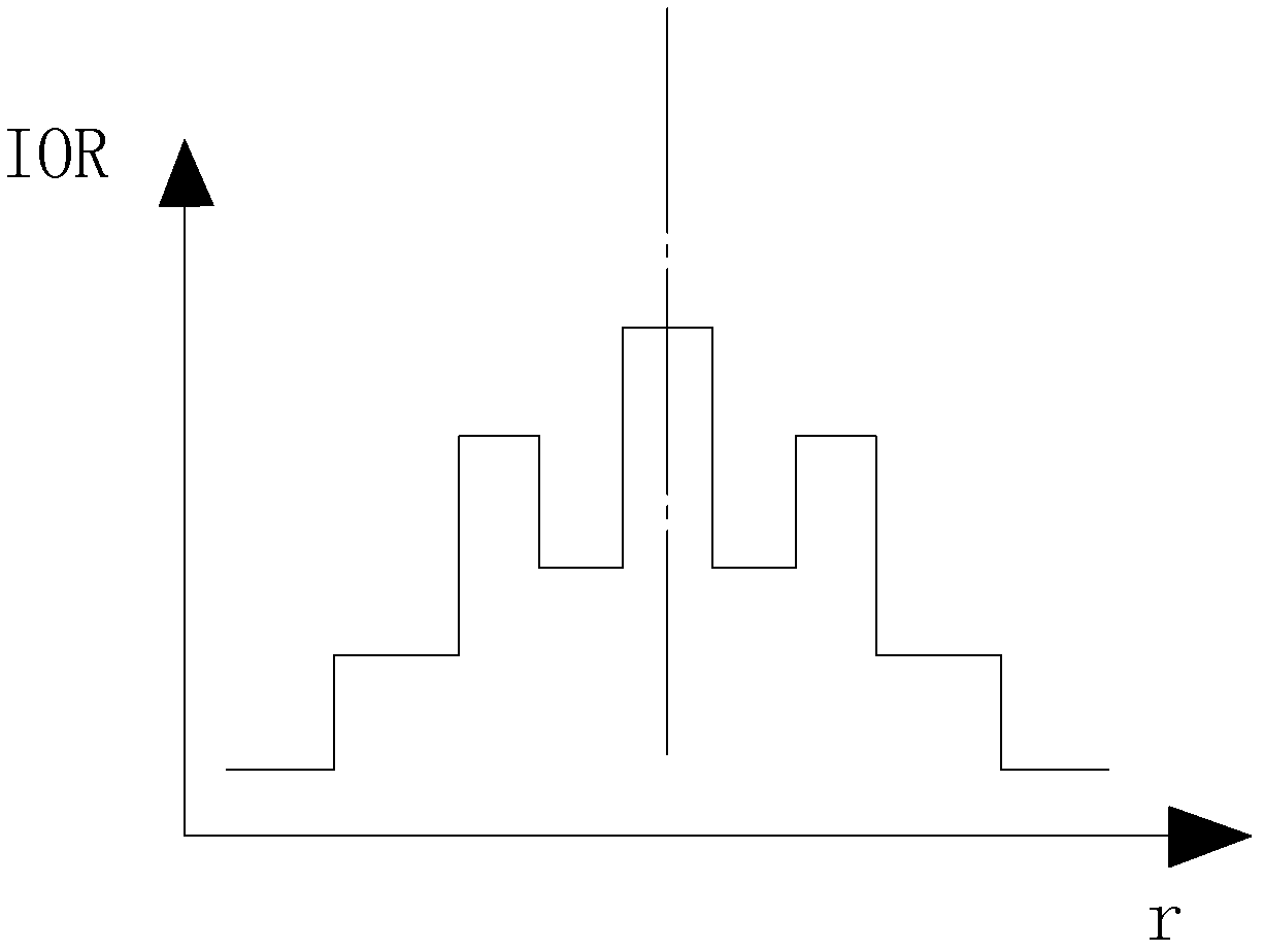
[0024] Such as figure 1 , figure 2 A plastic optical fiber with a W-shaped refractive index distribution is shown, which is radially distributed from the center to the edge, and sequentially includes a core 1, a cladding 2, a cladding 2 and a cladding 4. The core 1 The refractive index of cladding layer 1 is greater than the refractive index of cladding layer 1, the refractive index of cladding layer 2 3 is greater than the refractive index of cladding layer 2 and cladding layer 3 4, and the outer side of cladding layer 3 4 is a protective layer 5; and the cladding layer Two 3 and cladding three 4 are made of polymer materials.

[0025] When optical signals are injected into the end face of a plastic optical fiber with a W-shaped refractive index distribution, there are optical signals in the core 1, cladding 2, cladding 2 3 and cladding 3 4, but after a short transmission distance, the cladding 1 Part of the optical signal in 2 is coupled into the core 1, part of it is cou...


PUM


Abstract

The invention discloses plastic optical fiber with W-shaped refractive index distribution. The plastic optical fiber sequentially comprises a fiber core, a first wrapping layer, a second wrapping layer and a third wrapping layer, wherein the fiber core, the first wrapping layer, the second wrapping layer and the third wrapping layer are distributed from the center to the edge of the plastic optical fiber along the radial direction. A refractive index of the fiber core is larger than that of the first wrapping layer. The refractive index of the second wrapping layer is larger than that of the first wrapping layer and that of the third wrapping layer. A protection layer is arranged outside the third wrapping layer. The second wrapping layer and the third wrapping layer are made of high molecular materials. According to the plastic optical fiber with W-shaped refractive index distribution, refractive index distribution of the radial direction of the optical fiber is set into a W shape so that two optical signal transmission channels are formed. When situations such as slight bend, curve, deformation or temperature change occur on the optical fiber, the purpose of monitoring in a distributed mode is achieved by means of detection of change of optical signals between the two optical signal channels. The optical fiber is convenient to use and low in cost, and has good application prospect.

Description

technical field [0001] The invention relates to an optical fiber, in particular to a plastic optical fiber with a W-shaped refractive index distribution. Background technique [0002] The optical fiber perimeter sensing monitoring system is a new security system, which has many advantages such as anti-electromagnetic interference and long monitoring distance. In the current optical fiber perimeter sensing monitoring system, the proportion of optical fiber interference method is relatively large, which has the advantages of It has the characteristics of low false negative rate and high precision, but its poor positioning ability and high false positive rate seriously affect its popularization and application. Compared with optical fiber interference, the optical fiber microbend sensing device has the advantages of low cost, positionability, and low false alarm rate, but it is difficult to combine with the fence or railing in the perimeter, and its practical application is ver...

Claims


Application Information

Patent Timeline
Patent Type & Authority Applications(China)
IPC IPC(8): G02B6/036G02B6/02
Inventor 杜兵
Owner XIAN JINHE OPTICAL TECH
Learn More